Prime lens

A fixed-focus lens and lens technology, which is applied in the field of fixed-focus lenses, can solve the problems of reducing the authenticity of restored images and image edge deformation, and achieve the effects of good processing and assembly tolerances, small image deformation, and good manufacturability

Pending Publication Date: 2021-02-02
舜宇光学(中山)有限公司
View PDF0 Cites 4 Cited by
  • Summary
  • Abstract
  • Description
  • Claims
  • Application Information

AI Technical Summary

Problems solved by technology

Generally, video conferencing lenses require a wider horizontal field of view and a more realistic restoration of the picture. General wide-angle lenses have certain distortions, which lead to distortion at the edge of the image screen, which in turn reduces the authenticity of the restored image.

Method used


Image

  • Prime lens
  • Prime lens
  • Prime lens

Examples


Embodiment approach 1

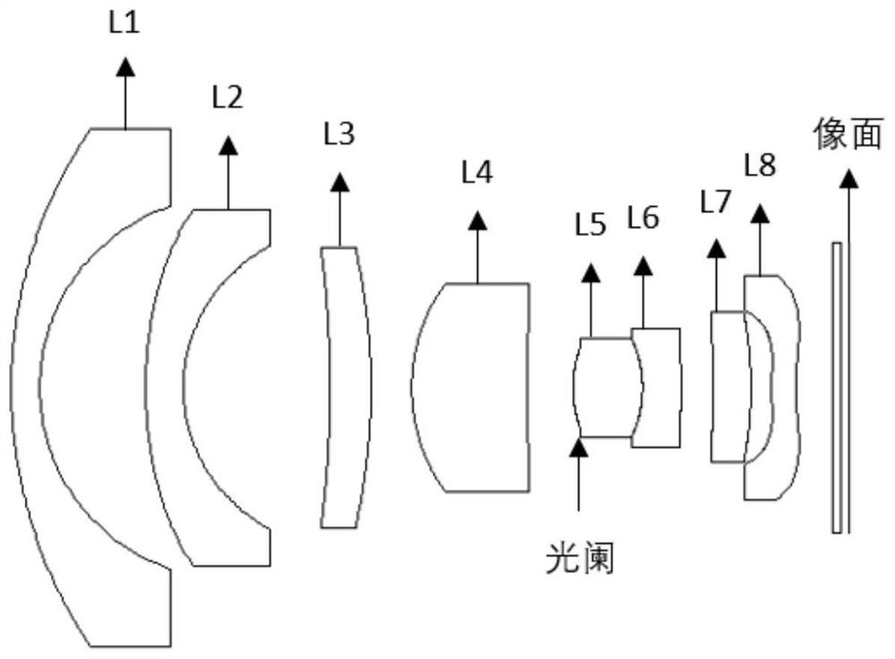
[0056] figure 1 It is a diagram schematically showing the structure of a fixed-focus lens according to Embodiment 1 of the present invention.

[0057] In this embodiment, the FNO of the fixed-focus lens is 2.2, the total length of the lens is 15.98 mm, the diagonal field angle is 105.8°, and the aperture is located on the object side of the fifth lens L5.

[0058] The following table 2 lists the relevant parameters of each lens of the present embodiment, including surface type, radius of curvature, thickness, refractive index of material, Abbe number:

[0059]

[0060]

[0061] Table 2

[0062] Table 3 lists the aspheric coefficients of each aspheric lens in this embodiment, K is the quadric surface constant of the surface, and A, B, C, D, E, and F are respectively the fourth order, sixth order, and eighth order , 10th order, 12th order, and 14th order aspheric coefficients.

[0063] Face number K A B C D E F S3 -0.2323 7.84E-03 -7.72E-04 6.19...

Embodiment approach 2

[0067] Figure 6 It is a diagram schematically showing the structure of a fixed-focus lens according to Embodiment 2 of the present invention.

[0068] In this embodiment, the FNO of the fixed-focus lens is 2.18, the total length of the lens is 15.64 mm, the diagonal field angle is 104.8°, and the aperture is located on the object side of the fifth lens L5.

[0069] The following table 4 lists the relevant parameters of each lens of this embodiment, including surface type, radius of curvature, thickness, refractive index of material, Abbe number:

[0070] Face number surface type R value thickness Refractive index Abbe number S0(OBJ) sphere Infinity Infinity S1 sphere 18.6743 1.2300 1.50 69.0 S2 sphere 6.7370 1.6222 S3 Aspherical 11.7780 0.7798 1.49 60.0 S4 Aspherical 3.3453 1.7987 S5 sphere -12.3657 2.1999 1.53 50.0 S6 sphere -7.2147 0.1353 S7 sphere 4.8521 1.5744 1.6...

Embodiment approach 3

[0078] Figure 11 is a schematic diagram showing the structure of a fixed-focus lens according to Embodiment 3 of the present invention.

[0079] In this embodiment, FNO of the fixed-focus lens is 2.16, the total length of the lens is 15.85 mm, the diagonal field angle is 106.9°, and the aperture is located between the fourth lens L4 and the fifth lens L5.

[0080] The following table 6 lists the relevant parameters of each lens of this embodiment, including surface type, radius of curvature, thickness, refractive index of material, Abbe number:

[0081] Face number surface type R value thickness Refractive index Abbe number S0(OBJ) sphere Infinity Infinity S1 sphere 16.0000 0.9145 1.45 69.0 S2 sphere 4.2357 1.3215 S3 Aspherical 9.0852 1.0561 1.68 94.0 S4 Aspherical 3.4273 1.6275 S5 sphere -24.5073 0.6746 1.49 71.0 S6 sphere -13.9635 1.1014 S7 sphere 3.9258 1.9746 1.77...


PUM


Abstract

The invention relates to a prime lens along a direction from an object side to an image side. The prime lens sequentially comprises a first lens (L1) with negative focal power, a second lens (L2) withnegative focal power, a third lens (L3) with positive focal power, a fourth lens (L4) with positive focal power, a fifth lens (L5) with positive focal power, a sixth lens (L6) with negative focal power, a seventh lens (L7) with positive focal power and an eighth lens (L8) with negative focal power. The prime lens has the advantages of being low in distortion, high in pixel, small in size and freeof virtual focus within the temperature range of 0-80 DEG C.

Description

technical field [0001] The invention relates to the technical field of optical system and device design, in particular to a fixed-focus lens. Background technique [0002] With the development of information technology, video conferencing is widely used in remote communication management of enterprises. Video conferencing pays more and more attention to the fidelity and interactivity of the meeting. In video conferencing, the imaging optical system of the camera is a very important part. The choice of imaging optical system has a significant impact on the practical effect of video conferencing. Generally, video conferencing lenses require a wider horizontal field of view and a more realistic restoration of the picture. General wide-angle lenses have certain distortions, which lead to distortion at the edge of the image screen, which in turn reduces the authenticity of the restored image. Contents of the invention [0003] The object of the present invention is to solve th...

Claims


Application Information

Patent Timeline
Patent Type & Authority Applications(China)
IPC IPC(8): G02B13/18
CPCG02B13/18
Inventor 张圆冯世杰
Owner 舜宇光学(中山)有限公司
Why Eureka
Try Eureka