Vision-based vehicle positioning method and device and vehicle-mounted terminal

A vehicle positioning and vision technology, applied in the details of processing steps, image data processing, instruments, etc., can solve problems such as inability to perform visual positioning, low visual positioning effectiveness, and difficulty in high-precision maps.

Pending Publication Date: 2021-02-02
BEIJING MOMENTA TECH CO LTD
View PDF4 Cites 2 Cited by
  • Summary
  • Abstract
  • Description
  • Claims
  • Application Information

AI Technical Summary

Problems solved by technology

However, when there are few landmarks or even no landmarks in the scene, it is difficult for the high-precision map to give enough effective information for visual positioning; or, when the landmarks cannot completely match the high-precision map due to occlusion or aging, the visual positioning may not be possible
All of the above lead to less effective visual localization

Method used


Image

  • Vision-based vehicle positioning method and device and vehicle-mounted terminal
  • Vision-based vehicle positioning method and device and vehicle-mounted terminal
  • Vision-based vehicle positioning method and device and vehicle-mounted terminal

Examples


Embodiment approach 1

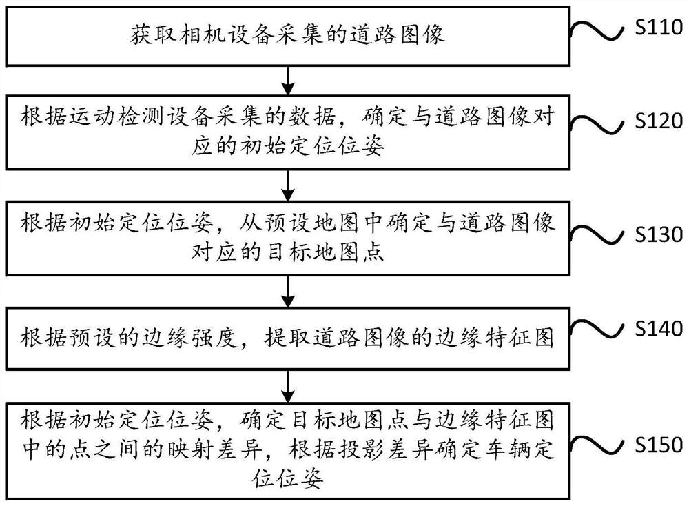
[0155] Embodiment 1: According to the value of the estimated pose, the transformation matrix between the world coordinate system and the camera coordinate system is determined, and according to the transformation matrix and the projection relationship between the camera coordinate system and the image coordinate system, the target map The point is mapped to the image coordinate system to obtain the first mapped position of the target map point, and the projection difference between the first mapped position and the position of the point in the edge feature map in the image coordinate system is calculated.

[0156] Wherein, the camera coordinate system is the three-dimensional coordinate system where the camera device is located, and the image coordinate system is the coordinate system where the road image is located. The estimated pose is the pose of the vehicle in the world coordinate system. According to the value of the estimated pose, the transformation matrix between the w...

Embodiment approach 2

[0160] Embodiment 2: Determine the transformation matrix between the world coordinate system and the camera coordinate system according to the value of the estimated pose. According to the transformation matrix and the projection relationship between the camera coordinate system and the image coordinate system, the edge feature map The points of are mapped to the world coordinate system, the second mapped position of the point in the edge feature map is obtained, and the projection difference between the second mapped position and the position of the target map point in the world coordinate system is calculated.

[0161] To sum up, in this embodiment, according to the mutual conversion relationship between the world coordinate system, the camera coordinate system and the image coordinate system, the position information of the target map point can be mapped to the image coordinate system, or the point in the edge feature map can be mapped to To the world coordinate system, spec...


PUM


Abstract

The embodiment of the invention discloses a vision-based vehicle positioning method and device and a vehicle-mounted terminal. The method comprises the following steps: acquiring a road image acquiredby camera equipment; determining an initial positioning pose corresponding to the road image according to the data acquired by the motion detection equipment; determining a target map point corresponding to the road image from a preset map according to the initial positioning pose; extracting an edge feature map of the road image according to preset edge intensity; determining a mapping difference between the target map point and a point in the edge feature map according to the initial positioning pose, and determining a vehicle positioning pose according to the projection difference, whereinthe initial positioning pose is a pose in a world coordinate system where a preset map is located, and each map point in the preset map is obtained by performing three-dimensional reconstruction andselection on points in the edge feature map of the sample road image in advance. By applying the scheme provided by the embodiment of the invention, the effectiveness of positioning the vehicle basedon vision can be improved.

Description

technical field [0001] The present invention relates to the technical field of intelligent driving, in particular to a vision-based vehicle positioning method, device and vehicle-mounted terminal. Background technique [0002] In the field of intelligent driving technology, vehicle positioning is an important part of intelligent driving. Usually, when the vehicle is driving, the vehicle pose can be determined according to the satellite positioning system. However, when the vehicle travels to a scene with weak or no satellite signal, in order to accurately determine the positioning pose of the vehicle, it can be positioned based on visual positioning. [0003] Vision-based positioning is usually based on the matching between the semantic information of the road image collected by the camera device and the semantic information in the high-precision map. The semantic information in the high-precision map is modeled based on common landmarks on the road. Markers generally inc...

Claims


Application Information

Patent Timeline
Patent Type & Authority Applications(China)
IPC IPC(8): G06T7/73G06T17/05G06T7/246G06T7/13G01C21/20G01C21/30
CPCG06T7/73G06T17/05G06T7/246G06T7/13G01C21/30G01C21/20G06T2207/30248G06T2200/08
Inventor 李天威徐抗刘一龙童哲航
Owner BEIJING MOMENTA TECH CO LTD
Why Eureka
Try Eureka