
Plasma etching equipment

A plasma and etching equipment technology, applied in the field of plasma etching equipment, can solve problems such as difficult to meet process requirements

Active Publication Date: 2021-02-02
ADVANCED MICRO FAB EQUIP INC CHINA
View PDF16 Cites 0 Cited by
  • Summary
  • Abstract
  • Description
  • Claims
  • Application Information

AI Technical Summary

Problems solved by technology

[0004] However, the distance between the upper electrode and the lower electrode of the existing capacitively coupled plasma etching device is fixed, making it difficult for the capacitively coupled plasma etching device to meet different process requirements

Method used


Image

  • Plasma etching equipment
  • Plasma etching equipment
  • Plasma etching equipment

Examples


Embodiment Construction

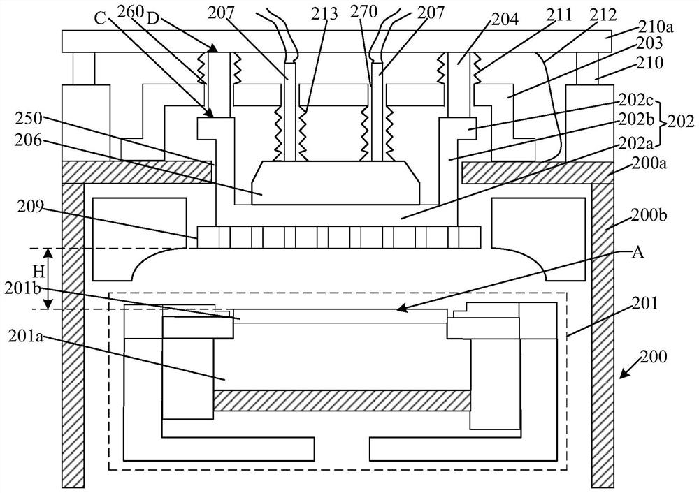
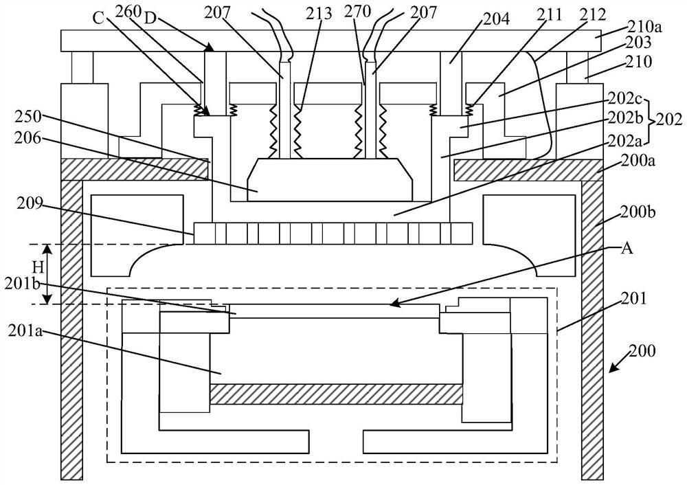
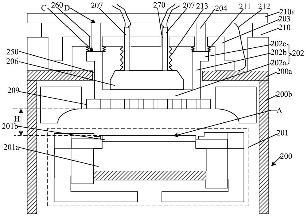
[0028] In order to solve the above technical problems, the technical solution of the present invention provides a plasma etching device, which can linearly adjust the distance between the upper electrode assembly and the lower electrode assembly to meet the needs of different processing techniques. Specifically, a plasma etching equipment, comprising: a reaction chamber, the top of the reaction chamber has a first opening; a lower electrode assembly located at the bottom of the reaction chamber, the lower electrode assembly includes a bearing surface, the The carrying surface is used to carry the substrate to be processed; the mounting substrate located in the first opening, there is a gap between the mounting substrate and the side wall of the first opening; the fixing part located at the top of the reaction chamber, the fixing The portion surrounds the mounting substrate, and the fixing portion has a second opening; the connecting portion, the connecting portion passes throug...


PUM


Abstract

The invention discloses plasma etching equipment. The plasma etching equipment comprises a reaction chamber, a lower electrode assembly, mounting substrate, a fixing part, a connecting part, a drivingdevice, and a first corrugated pipe; a first opening is formed in the top of the reaction chamber; the lower electrode assembly is located at the bottom of the interior of the reaction chamber; the lower electrode assembly comprises a bearing surface used for bearing a to-be-processed substrate; the mounting substrate is located in the first opening, and a gap is formed between the mounting substrate and the side wall of the first opening; the fixing part is positioned outside the top of the reaction chamber, and a second opening is formed in the fixing part; the connecting part penetrates through the second opening, a gap is formed between the connecting part and the side wall of the second opening, the connecting part comprises a first end and a second end which are opposite to each other, and the first end is connected with the mounting substrate; the driving device is connected with the second end and can drive the mounting substrate to move in the direction perpendicular to the bearing surface; the first corrugated pipe surrounds the connecting part and is used for maintaining the reaction chamber to be a closed space. The plasma etching equipment can meet different process requirements.

Description

technical field [0001] The invention relates to the field of semiconductors, in particular to a plasma etching device. Background technique [0002] In the semiconductor process, the process of etching the semiconductor material generally includes a dry etching process or a wet etching process, wherein, since the dry etching process using plasma for etching can effectively control the size of the etching opening The size has become the most mainstream etching process at present. Existing processes usually use glow discharge, radio frequency signal, corona discharge, etc. to form plasma. Among them, when using radio frequency signals to form plasma, the density and energy of the formed plasma can be controlled by adjusting the processing gas composition, frequency of radio frequency power, coupling mode of radio frequency power, air pressure, temperature and other parameters, so as to optimize the plasma treatment effect . Therefore, in existing semiconductor etching devic...

Claims


Application Information

Patent Timeline
Patent Type & Authority Applications(China)
IPC IPC(8): H01J37/20H01J37/02H01J37/18H01J37/24H01J37/30H01J37/305
CPCH01J37/3056H01J37/3002H01J37/20H01J37/023H01J37/18H01J37/24
Inventor 黄允文倪图强梁洁赵金龙
Owner ADVANCED MICRO FAB EQUIP INC CHINA
Learn More