
Temperature monitoring device, system and method of power grid terminal, medium and processor

A monitoring device and power grid technology, applied in circuit devices, electrical devices, thermometers using electrical/magnetic components that are directly sensitive to heat, etc. problems, to achieve the effect of improving safety and eliminating the possibility of burnout or fire

Pending Publication Date: 2021-02-02
BEIJING SMARTCHIP MICROELECTRONICS TECH COMPANY +4
View PDF0 Cites 1 Cited by
  • Summary
  • Abstract
  • Description
  • Claims
  • Application Information

AI Technical Summary

Problems solved by technology

[0003] However, there is always an important fault in the current grid terminal, that is, the terminal heating problem caused by the current of the grid terminal
For this problem, the current smart grid infrastructure either does not have monitoring capabilities, or can only perform simple heat detection and alarm, and cannot be controlled in time
Therefore, the existing technology is often to trace the cause and rectify after the power grid terminal heating problem causes power outage, maintenance or even a fire accident, lacking the fundamental ability to predict and prevent the problem from reoccurring

Method used


Image

  • Temperature monitoring device, system and method of power grid terminal, medium and processor
  • Temperature monitoring device, system and method of power grid terminal, medium and processor
  • Temperature monitoring device, system and method of power grid terminal, medium and processor

Examples


Embodiment Construction

[0031] The specific implementation manners of the embodiments of the present invention will be described in detail below in conjunction with the accompanying drawings. It should be understood that the specific implementation manners described here are only used to illustrate and explain the embodiments of the present invention, and are not intended to limit the embodiments of the present invention.

[0032] It should be noted that the grid terminal in the embodiment of the present invention is also often referred to as a grid node in the field, and the two can be used equally.

[0033] In addition, in the embodiments of the present invention, "electrical connection" is used to describe the signal connection between two components, such as control signals and feedback signals, and the electrical power connection between two components, which can be wired connection or It may be a wireless connection, and the "electrical connection" referred to may be a direct electrical connect...


PUM


Abstract

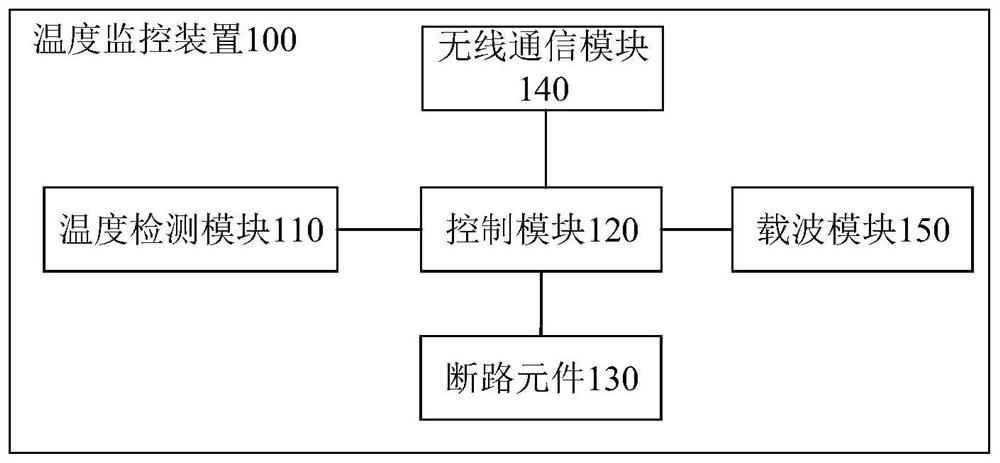
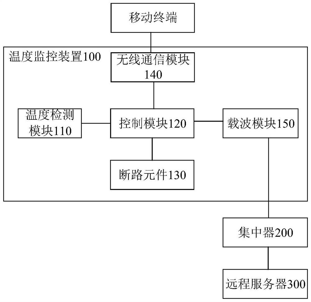
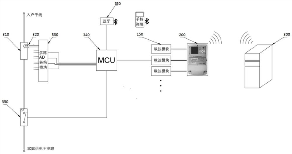
Embodiments of the invention provide a temperature monitoring device, system and method for a power grid terminal, a medium and a processor, belonging to the technical field of temperature sensors andpower Internet of Things. The power grid terminal is arranged on a power supply line of a power grid. The temperature monitoring device of the power grid terminal comprises: a temperature detection module, which is suitable for setting the position of the power grid terminal and is used for detecting the real-time temperature of the power grid terminal; and a control module. which is electricallyconnected with the temperature detection module and is used for acquiring the real-time temperature, detected by the temperature detection module, of the power grid terminal and cutting off the powersupply line when the real-time temperature exceeds a set temperature or the rising rate of the real-time temperature exceeds a set rate. According to the invention, the temperature of the power gridterminal can be monitored, and when the temperature rises suddenly or exceeds the set temperature, the power supply line can be cut off in time to ensure the safety of the power grid terminal.

Description

technical field [0001] The present invention relates to the technical field of temperature sensor and electric power internet of things, in particular to a temperature monitoring device, system, method, medium and processor of a power grid terminal. Background technique [0002] At present, the power demand in various countries tends to be saturated. After years of development, the traditional power grid has been able to meet the relatively sufficient power transmission and distribution supply capacity. However, it only achieves sufficient power, while problems such as high management costs and waste caused by uneven distribution are still prominent. As a result, the smart grid came into being, which organically integrates information technology, sensor technology, automatic control technology and grid infrastructure to obtain panoramic information of the grid, and based on this, it can detect or predict possible failures in time. [0003] However, there is always an import...

Claims


Application Information

Patent Timeline
Patent Type & Authority Applications(China)
IPC IPC(8): H02J13/00H02H5/04H02H7/26G01K7/00G01K7/22
CPCG01K7/00G01K7/22H02H5/04H02H7/26H02J13/00001H02J13/00002H02J13/00006H02J13/00022H02J13/00026Y02B90/20Y02E60/00Y04S40/12Y04S40/126
Inventor 庞振江李延王文赫侯战斌王峥张谦郭彦杜君陈伟娜付青琴段晓萌江小强马日红尉中杰朱京蓥
Owner BEIJING SMARTCHIP MICROELECTRONICS TECH COMPANY
Learn More