Concrete recovery sand-stone separation device for constructional engineering

A technology for sand and gravel separation and construction engineering, which is applied in the field of sand and gravel separation, and can solve problems such as dehydration of fine sand

Pending Publication Date: 2021-02-05
魏雪
View PDF9 Cites 4 Cited by
  • Summary
  • Abstract
  • Description
  • Claims
  • Application Information

AI Technical Summary

Problems solved by technology

[0005] The purpose of the present invention is to solve the shortcomings of the prior art that the fine sand in the mud is not dehydrated, and propose a concrete recovery sand and stone separation device for construction engineering

Method used


Image

  • Concrete recovery sand-stone separation device for constructional engineering
  • Concrete recovery sand-stone separation device for constructional engineering
  • Concrete recovery sand-stone separation device for constructional engineering

Examples


Embodiment 1

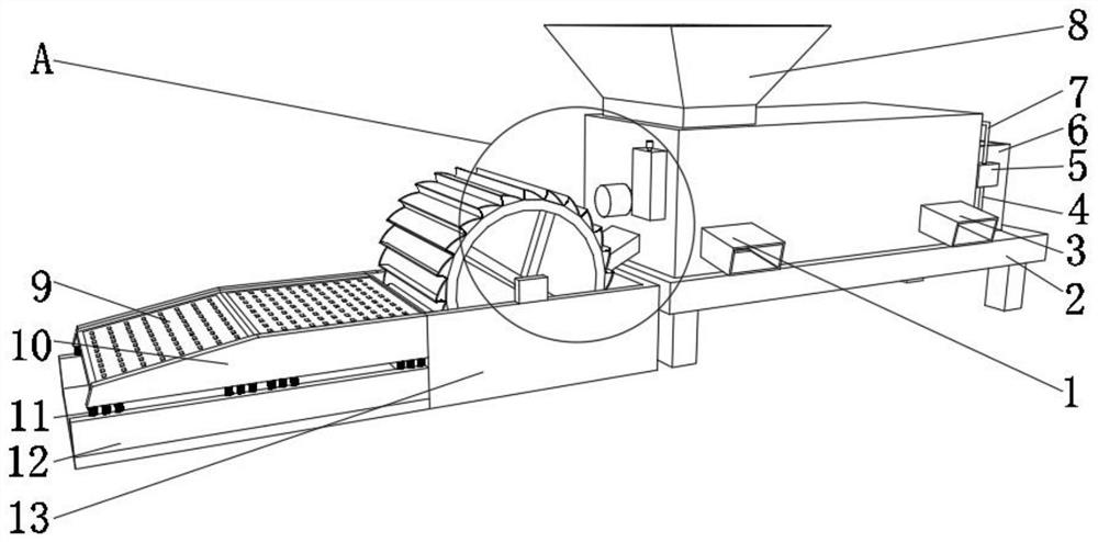
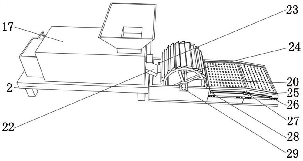
[0032] A kind of concrete recycling sandstone separation device for construction engineering, such as Figure 1-5As shown, it includes a base 2 and a sedimentation tank 13. The top of the base 2 is fixed with a box body 17 by bolts, the outer wall of one side of the box body 17 is fixed with a water tank 6 by bolts, and the top of the box body 17 is screwed. Bucket 8, one side outer wall of box body 17 is fixed with stone outlet 3 and sand outlet 1 by thread, one side outer wall of box body 17 is fixed with controller 15 by bolt, and the top outer wall of controller 15 is fixed with alarm 16 by bolt , the inside of the box 17 is provided with a separation mechanism, the top inner wall of the box 17 is provided with a flushing mechanism, one side of the outer wall of the box 17 is fixed with a discharge pipe 22, and one side of the inner wall of the sedimentation tank 13 is fixed with a liquid level sensor 23, and the liquid level sensor 23 is electrically connected with the al...

Embodiment 2

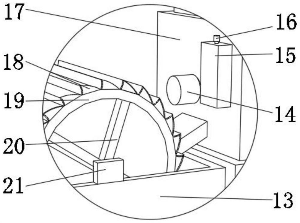
[0038] A kind of concrete recycling sandstone separation device for construction engineering, such as figure 1 , 3 , 4, and 5, in order to solve the problem of promoting the dehydration effect; this embodiment makes the following improvements on the basis of embodiment 1: comprising a sedimentation tank 13, one side of the outer wall of the sedimentation tank 13 is fixed with a fixed seat 12 by bolts , the top of the fixing seat 12 is fixed with more than three springs 11 by bolts, the top end of the springs 11 is fixed with two fixed plates-10 by bolts, and the outer wall of the opposite side of the two fixed plates-10 is fixed with two vibrating screens by bolts 9. The outer wall on one side of one of the fixing plates one 10 is fixed with two pulleys one 26 and two pulleys 27 through bearings, one of the outer walls on one side of the pulley one 26 is fixed with an electric motor 28 through a rotating shaft, and the inner walls of the three transmission belts 25 are respect...


PUM


Abstract

The invention discloses a concrete recovery sand-stone separation device for constructional engineering, and relates to the technical field of gravel separation. In order to solve the problem of finesand water removal, the device specifically comprises a base and a sedimentation tank, a box body is fixed to the top of the base through bolts, a water tank is fixed to the outer wall of one side ofthe box body through bolts, a feeding hopper is fixed to the top of the box body through threads, a stone outlet and a sand outlet are fixed to the outer wall of one side of the box body through threads, and a controller is fixed to the outer wall of one side of the box body through bolts; and an alarm is fixed to the outer wall of the top of the controller through bolts, a separation mechanism isarranged in the box body, a flushing mechanism is arranged on the inner wall of the top of the box body, and a discharging pipe is fixed to the outer wall of one side of the box body through threads.A second motor is started, so that the output end of the second motor drives a connecting rod to rotate, a rotary drum and a filtering frame can be driven to rotate through a fixing rod, mud enters the filtering frame through rotation of the rotary drum, and the mud is dewatered due to gravity.

Description

technical field [0001] The invention relates to the technical field of sand and gravel separation, in particular to a concrete recycling sand and gravel separation device for construction engineering. Background technique [0002] With the continuous development of China's large-scale construction, people's demand for concrete is also increasing, which makes it particularly important to recycle some waste concrete. The existing concrete cleaning and separation equipment has limited separation effect on solids, and It is difficult to completely separate sand and stones, not only can not complete the recycling of sand and stones, but also can not complete the recycling of sand and stones, which is a waste of resources and pollutes the environment. [0003] After retrieval, the Chinese patent application number is CN107983473B, which discloses a kind of concrete recycling sandstone separation device for construction engineering, including a support plate, a first support frame ...

Claims


Application Information

Patent Timeline
Patent Type & Authority Applications(China)
IPC IPC(8): B03B7/00B03B9/06B03B11/00
CPCB03B7/00B03B9/063B03B11/00Y02W30/52
Inventor 魏雪
Owner 魏雪
Why Eureka
Try Eureka