Yarn guiding device with dust removing function

A technology of yarn guide device and function, which is applied in the field of yarn guide device with dust cleaning function, which can solve the problems of easy messy yarn, easy yarn breakage, and inability to adjust yarn tension, etc., so as to achieve the effect of ensuring reliability

Active Publication Date: 2021-02-05
衡阳新新纺织机械有限公司
View PDF11 Cites 5 Cited by
  • Summary
  • Abstract
  • Description
  • Claims
  • Application Information

AI Technical Summary

Problems solved by technology

[0004] The above-mentioned patents have the following disadvantages: due to the difference in the speed of the textile machine when eating yarn, and in the actual yarn guiding process, a certain tension needs to be caused in the yarn, and when the tension

Method used


Image

  • Yarn guiding device with dust removing function
  • Yarn guiding device with dust removing function
  • Yarn guiding device with dust removing function

Examples


Embodiment 1

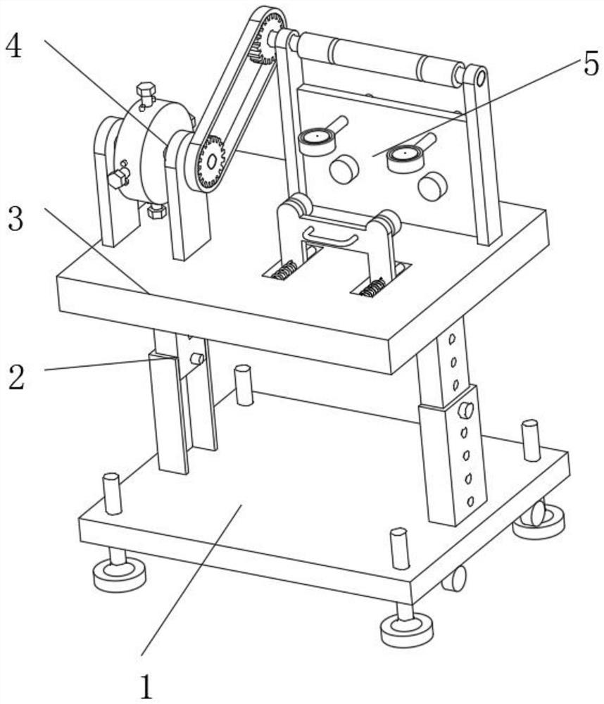
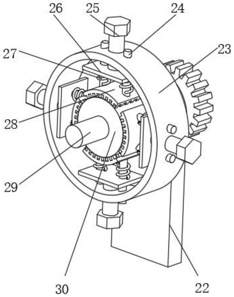
[0034] A yarn guide device with dust removal function, such as Figure 1-4As shown, including a base 1, the top outer wall of the base 1 is connected with a workbench 3 through a lifting mechanism 2, and the top outer wall of the workbench 3 is respectively provided with an adaptive adjustable damping mechanism 4 and a yarn guide mechanism 5. The self-adaptive adjustable damping mechanism 4 includes an outer cover 23, a friction wheel 30 and four groups of friction assemblies. The outer cover 23 is connected with a support plate 3 22 through rotation of a rotating shaft, and the support plate 3 22 is fixed on the top outer wall of the workbench 3 by bolts. Four sets of friction assemblies are arranged in a circular array on the inner wall of the outer cover 23. The friction assemblies include a transition plate 26 and a friction plate 28. The top outer wall of the friction plate 28 is integrally formed with a slide bar 3 24, and the slide bar 3 24 slides Connected on the inner...

Embodiment 2

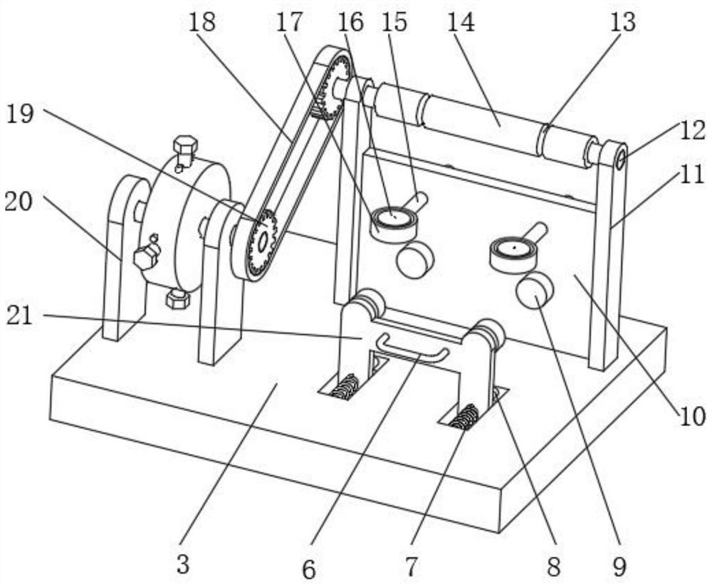
[0037] A yarn guide device with dust removal function, such as figure 1 , 2 As shown, in order to solve the yarn guiding problem; this embodiment makes the following improvements on the basis of Embodiment 1: the yarn guiding mechanism 5 includes a clamping assembly and a yarn guiding assembly, and the clamping assembly includes four thimbles 9, fixed plate 10 and clamping plate 21, the fixed plate 10 is fixed on the top outer wall of the workbench 3 by bolts, wherein two thimbles 9 are rotatably connected to the outer wall of the fixed plate 10, and the other two thimbles 9 pass through The rotating shaft is rotatably connected to the inner wall of the clamping plate 21, the inner wall of the workbench 3 is provided with a chute, the inner wall of the chute is fixed with a slide bar 8 by bolts, and the clamping plate 21 is slidably connected to the outer wall of the slide bar 8, And the outer wall of the slide bar one 8 is covered with a spring one 7, the outer wall of the c...

Embodiment 3

[0040] A yarn guide device with dust removal function, such as figure 1 , 5 As shown, in order to solve the yarn guiding problem; this embodiment makes the following improvements on the basis of Embodiment 2: the lifting mechanism 2 includes a lifting column 34 and a fixed column 38, and the two lifting columns 34 are fixed to the workbench by bolts 3 on the bottom outer wall, the two fixed columns 38 are fixed on the top outer wall of the base 1 by bolts, the lifting column 34 is slidably connected to one side of the fixed column 38, and the lifting column 34 and the inner wall of the fixed column 38 Open the uniform adjustment hole 1 35 and the adjustment hole 2 37 respectively, one of the adjustment holes 35 and the inner wall of the adjustment hole 2 37 cooperate with the same elastic pin 36, and the bottom outer wall of the base 1 is provided with ten thousand To the wheel 31, the inner walls of the four corners of the base 1 are all threadedly connected with a lifting s...


PUM


Abstract

The invention discloses a yarn guiding device with a dust removing function, and relates to the technical field of textile. The problem of self-adaptive tension adjustment is solved. The yarn guidingdevice with the dust removing function specifically comprises a base, a workbench is connected to the outer wall of the top of the base through a lifting mechanism, and a self-adaptive adjustable damping mechanism and a yarn guiding mechanism are arranged on the outer wall of the top of the workbench; and the self-adaptive adjustable damping mechanism comprises an outer cover, a friction wheel andfour friction assemblies, the outer cover is rotationally connected with a third supporting plate through a rotating shaft, and the third supporting plate is fixed to the outer wall of the top of theworkbench through bolts. According to the yarn guiding device with the dust removing function, a friction plate is in sliding connection with the outer cover through a third sliding rod, the outer cover is in transmission fit with the yarn guiding mechanism, when the yarn feeding speed is increased, the rotating speed of the outer cover is increased, a transition plate is relatively fixed, the friction plate is subjected to outward centrifugal force to balance the elastic force of second springs at the moment, therefore, tension is reduced, and the purpose of self-adaptively adjusting the tension according to the yarn feeding speed is achieved.

Description

technical field [0001] The invention relates to the technical field of textiles, in particular to a yarn guide device with a dust cleaning function. Background technique [0002] Spinning machinery needs to wind the yarn on the bobbin to form a yarn package after the yarn is formed, so as to facilitate subsequent transportation and other processing. When winding the yarn onto the bobbin, in order to avoid the yarn always overlapping At the same position of the bobbin, a yarn guide device needs to be set when the yarn is wound onto the bobbin. [0003] After retrieval, the Chinese patent publication number is the patent of CN111041706A, discloses a kind of rolling type yarn guiding device, comprises main frame, and described rolling type yarn guiding device also comprises first rolling column, second rolling column, yarn guiding rod, guide Yarn plate, stabilizer, stabilizer, one end of the stabilizer is fixedly connected with the main frame, the other end of the stabilizer i...

Claims


Application Information

Patent Timeline
IPC IPC(8): B65H59/10B65H57/14B65H54/70
CPCB65H59/10B65H57/14B65H54/702Y02W30/66
Inventor 曾贤通彭来深焦贤伟谭新球
Owner 衡阳新新纺织机械有限公司
Why Eureka
Try Eureka