Supercharge Your Innovation With Domain-Expert AI Agents!

Wire rod transmission detection device

A transmission detection and wire technology, applied in transportation and packaging, transportation of filamentous materials, textiles, etc., can solve the problems of limited use, waste of wire, complex structure, etc., to achieve flexible and convenient use, accurate detection results, high adjustable effects

Pending Publication Date: 2021-02-05
苏州盛达飞智能科技股份有限公司
View PDF13 Cites 0 Cited by
  • Summary
  • Abstract
  • Description
  • Claims
  • Application Information

AI Technical Summary

Problems solved by technology

[0002] Generally speaking, when a textile machine is performing textile operations, it will draw wires of various colors or materials from a plurality of wire drums separately or simultaneously, and weave each of the wires to complete the textile operation. When the wire of the drum is exhausted or broken, the textile machine continues to draw the wire of other wire drums for weaving, which causes the textile machine to weave defective products and leads to the problem of wire waste. Traditionally, the industry uses a A detection system to detect the wires delivered to the textile machine by each wire drum respectively, and when the wire of any wire drum is exhausted or broken, a stop signal is sent to the textile machine to stop the textile machine textile work
[0003] Existing detection systems all use the method of blocking visible light, so the structure is complex, and a certain light source environment must be created, otherwise it is easy to be affected by external ambient light, dust or dander, and cause misjudgment problems; and a detection The system can only detect one type of wire at a time. When it is necessary to weave multiple types of wires at the same time, it is difficult to monitor all types of wires separately, so the scope of use is limited.

Method used


Image

  • Wire rod transmission detection device

Examples


Embodiment Construction

[0019] The present invention will be described in further detail below in conjunction with the embodiments and accompanying drawings, so that those skilled in the art can implement it with reference to the description.

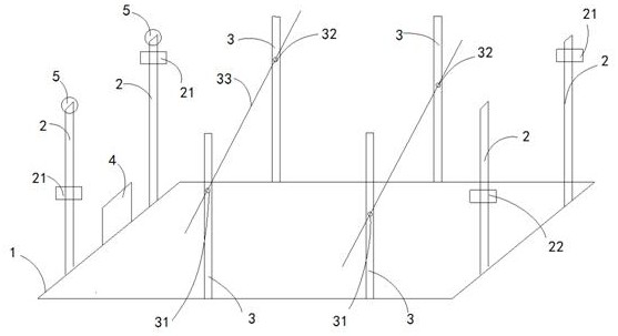
[0020] Such as figure 1 As shown, a wire transmission detection device includes: a fixed frame 1, on both sides of the fixed frame 1 there are several sets of adjustable first adjusting rods 2 symmetrically arranged to form several detection spaces, and the fixed frame 1 On the other two sides of the frame 1, there are several sets of adjustable second adjustment rods 3 arranged symmetrically, and the first adjustment rods 2 of each group are respectively provided with an infrared emitter 21 and an infrared light receiver 22. The second adjusting rod 3 has an inlet hole 31 and an outlet hole 32 correspondingly arranged for the wire to pass through; a wire transmission channel 33 is formed between each group of inlet holes 31 and outlet holes 32, so that the wi...


PUM


Abstract

The invention relates to a wire rod transmission detection device. The wire rod transmission detection device comprises a fixed frame, wherein two side faces of the fixed frame are provided with a plurality of groups of adjustable first adjusting rods which are symmetrically arranged to form a plurality of detection spaces, the other two side faces of the fixed frame are provided with a pluralityof groups of adjustable second adjusting rods which are symmetrically arranged, and an infrared light emitter and an infrared light receptor are respectively arranged on each group of first adjustingrods; the wire rod transmission detection device further comprises a controller and a plurality of warning indicators corresponding to the first adjusting rods respectively; the infrared light emitters are horizontally arranged and used for emitting infrared light beams; the infrared light receptors are horizontally arranged and used for receiving the infrared light beams; the signal output end ofeach infrared light receptor is connected with the signal input end of the controller, and each warning indicator is connected with the signal output end of the controller; and the controller is usedfor sending out an enabling signal to the warning indicator and / or a transmission device corresponding to the group when a certain infrared light receptor cannot receive the infrared light beams.

Description

technical field [0001] The invention relates to the field of wire transmission equipment, in particular to a wire transmission detection device. Background technique [0002] Generally speaking, when a textile machine is performing textile operations, it will draw wires of various colors or materials from a plurality of wire drums separately or simultaneously, and weave each of the wires to complete the textile operation. When the wire of the drum is exhausted or broken, the textile machine continues to draw the wire of other wire drums for weaving, which causes the textile machine to weave defective products and leads to the problem of wire waste. Traditionally, the industry uses a A detection system to detect the wires delivered to the textile machine by each wire drum respectively, and when the wire of any wire drum is exhausted or broken, a stop signal is sent to the textile machine to stop the textile machine Textile work. [0003] Existing detection systems all use t...

Claims


Application Information

Patent Timeline
IPC IPC(8): B65H63/032B65H63/08D03D51/18
CPCB65H63/0324B65H63/086D03D51/18B65H2701/31
Inventor 林志武高凌文杨滨
Owner 苏州盛达飞智能科技股份有限公司
Features
  • R&D
  • Intellectual Property
  • Life Sciences
  • Materials
  • Tech Scout
  • Unparalleled Data Quality
  • Higher Quality Content
  • 60% Fewer Hallucinations
Learn More