Filling device and method for waste air-raid shelter of pile foundation construction site

A technology of construction site and filling device, which is applied in filling, infrastructure engineering, construction, etc., can solve the problems of non-normal construction, easy bleeding and collapse, and high cost, and achieves the problem of filling quality, uniform concrete bubbles, and low cost. Effect

Active Publication Date: 2021-02-05
WUHAN SURVEYING GEOTECHN RES INST OF MCC
View PDF6 Cites 6 Cited by
  • Summary
  • Abstract
  • Description
  • Claims
  • Application Information

AI Technical Summary

Problems solved by technology

[0004] The purpose of the present invention is to solve the problem that when the rotary drilling rig constructs the cast-in-situ pile foundation and encounters a deep-buried air-raid shelter, it cannot be constructed normally. The traditional method of excavation and replacement is low in efficiency and high in cost. Accident, and provide a kind of filling device and method of abandoned air-raid shelter in pile foundation construction site, using this device and method can be efficient, safe, environment-friendly and reduce engineering cost filling abandoned air-raid structure cavity without excavation, and at the same time It can ensure that the filling body does not affect the pile foundation construction work of the rotary drilling rig, and the filled air-raid shelter can normally carry out the construction of bored piles

Method used


Image

  • Filling device and method for waste air-raid shelter of pile foundation construction site
  • Filling device and method for waste air-raid shelter of pile foundation construction site
  • Filling device and method for waste air-raid shelter of pile foundation construction site

Examples


Embodiment Construction

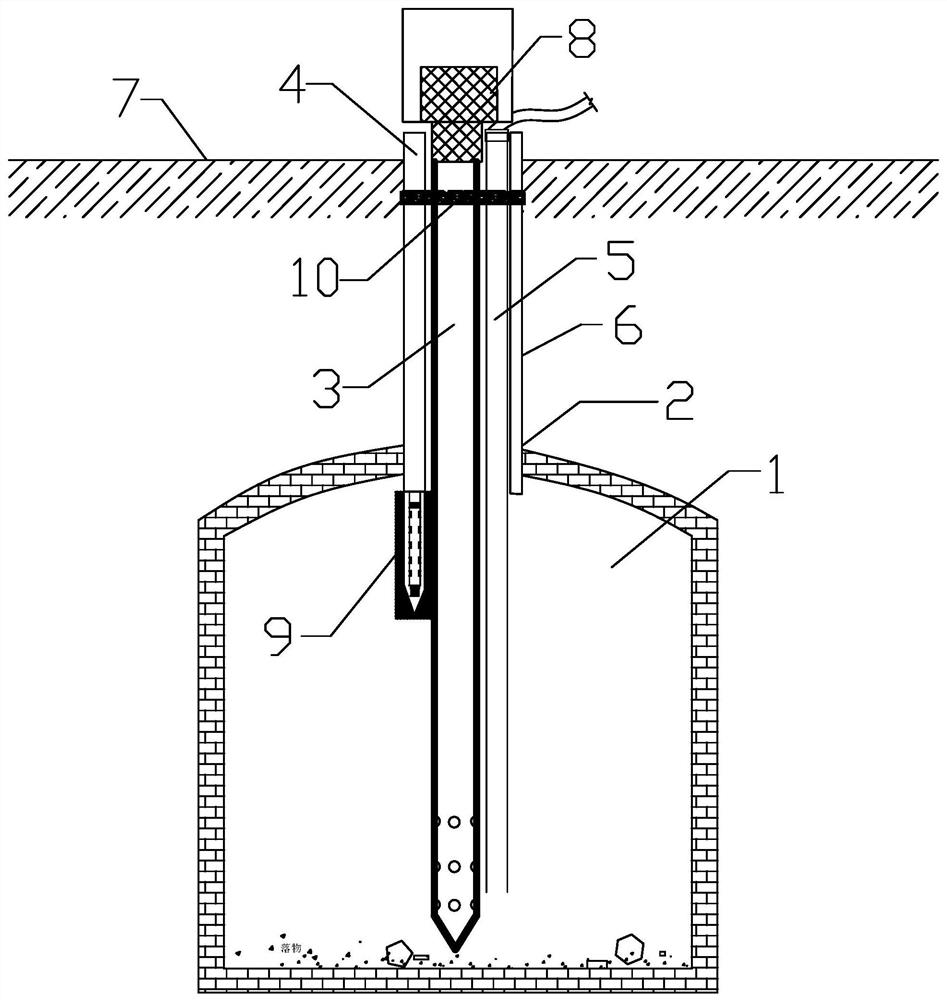
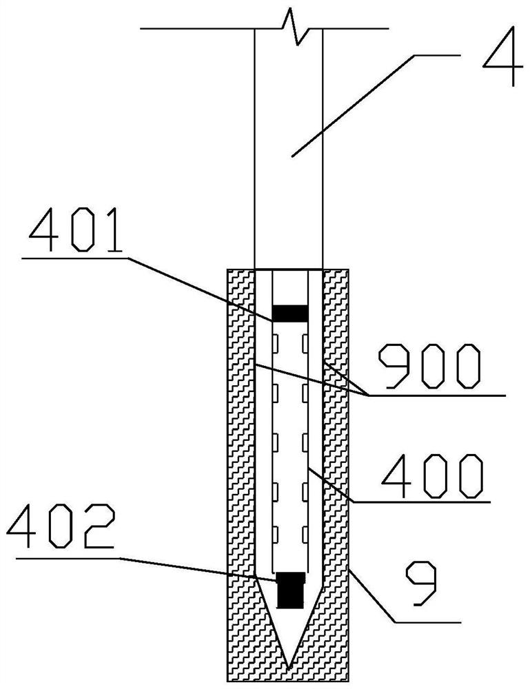
[0035] The present invention will be further described below in conjunction with drawings and embodiments. attached figure 1 The drawings for the embodiments are drawn in a simplified manner and are only used for the purpose of clearly and concisely illustrating the embodiments of the present invention. The following technical solutions shown in the drawings are specific solutions of the embodiments of the present invention, and are not intended to limit the scope of the claimed invention. Based on the embodiments of the present invention, all other embodiments obtained by persons of ordinary skill in the art without creative efforts fall within the protection scope of the present invention.

[0036] In the description of the present invention, it should be understood that the orientations or positional relationships indicated by the terms "upper", "lower", "inner", "outer", "left", "right" etc. are based on those shown in the accompanying drawings. Orientation or positional...


PUM


Abstract

The invention provides a filling device and method for a waste air-raid shelter of a pile foundation construction site. The filling method comprises the steps that a grouting drill hole is drilled above a waste air-raid shelter to be filled, a primary grouting pipe, a secondary grouting pipe, an air supply pipe and an air exhaust pipe are installed in the drill hole, the primary grouting pipe andthe air supply pipe vertically extend into the bottom of the air-raid shelter, the secondary grouting pipe and the air exhaust pipe vertically extend to the top of the air-raid shelter, firstly, the primary grouting pipe is connected with a grouting pump, the air supply pipe is connected with an air compressor, foam concrete grouting slurry is injected in a layered mode, the primary grouting pipeand the air supply pipe are pulled up all the way to the top of the air-raid shelter after grouting of each layer is completed, then the secondary grouting pipe is connected to inject the foam concrete grouting slurry for the second time, and air is not supplied during secondary grouting. The filling problem of the deep-buried air-raid shelter can be solved under the condition that excavation is not conducted, normal construction of a cast-in-situ bored pile can be guaranteed on a filled construction site, and the problems that when a rotary drilling rig constructs a cast-in-situ pile foundation, normal construction cannot be conducted on the deep-buried air-raid shelter, the site collapses and the like are solved.

Description

technical field [0001] The invention relates to an engineering construction method, in particular to a filling device and method for filling an abandoned air-raid shelter at a pile foundation construction site with foam concrete for filling the air-raid shelter when the cast-in-place pile foundation encountered by a rotary drilling rig encounters a deep-buried air-raid shelter. Background technique [0002] Air-raid shelters are caves dug during the Anti-Japanese War to avoid the bombing of enemy artillery fire and to protect personal and financial safety. Many air-raid shelters began at the beginning of the outbreak of the Anti-Japanese War. Most of them were made of brick walls and stones, and there were also large buildings with concrete structures. With the urban transformation and the loss of some data, these air defense engineering structures are buried underground, and many buildings are buried deep and complex in terrain. It is difficult to find them in the prelimina...

Claims


Application Information

Patent Timeline
Patent Type & Authority Applications(China)
IPC IPC(8): E02D17/18E02D15/02
CPCE02D15/02E02D17/18
Inventor 王辉姚东珂李亚威王晓东陈晓波
Owner WUHAN SURVEYING GEOTECHN RES INST OF MCC
Why Eureka
Try Eureka