Sealing device for jet engine oil chamber

A technology of sealing device and turbojet, which is applied in the direction of engine sealing, engine components, machines/engines, etc., can solve the problems of reducing the efficiency of brush seals, reducing efficiency, and oil coking, so as to prevent sticking together and improve Efficacy and life, little effect on performance

Active Publication Date: 2012-12-05
SN DETUDE & DE CONSTR DE MOTEURS DAVIATION S N E C M A
View PDF9 Cites 9 Cited by
  • Summary
  • Abstract
  • Description
  • Claims
  • Application Information

AI Technical Summary

Problems solved by technology

Seals, on the other hand, have the disadvantage of tending to cause coking of the oil in contact with them
Coking is the conversion of oil into a solid deposit; this is due to reheating of the oil and it sticks to the carbon fibers; it reduces the effectiveness of the brush seal
In addition, the friction of the bristles on the path of the rotating parts (designed to contact the bristle ends) also causes them to wear and therefore also reduce their effectiveness over time

Method used


Image

  • Sealing device for jet engine oil chamber
  • Sealing device for jet engine oil chamber
  • Sealing device for jet engine oil chamber

Examples


Embodiment Construction

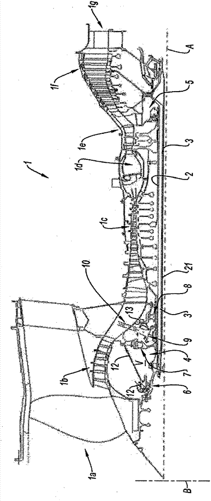
[0032] refer to figure 1 A turbojet engine 1 according to a first embodiment of the invention conventionally comprises a fan 1a, a low-pressure compressor 1b, a high-pressure compressor 1e, a combustion chamber 1d, a high-pressure turbine 1e, a low-pressure turbine 1f and an exhaust nozzle 1g. The high-pressure compressor 1e and the high-pressure turbine 1e are connected through a high-pressure shaft 2 and form a high-pressure core with it. The low-pressure compressor 1b and the low-pressure turbine 1f are connected via a low-pressure shaft 3 and form a low-pressure core therewith.

[0033] The turbojet engine 1 comprises static (or fixed) components and rotating components constituting in a known manner the different functional parts mentioned above.

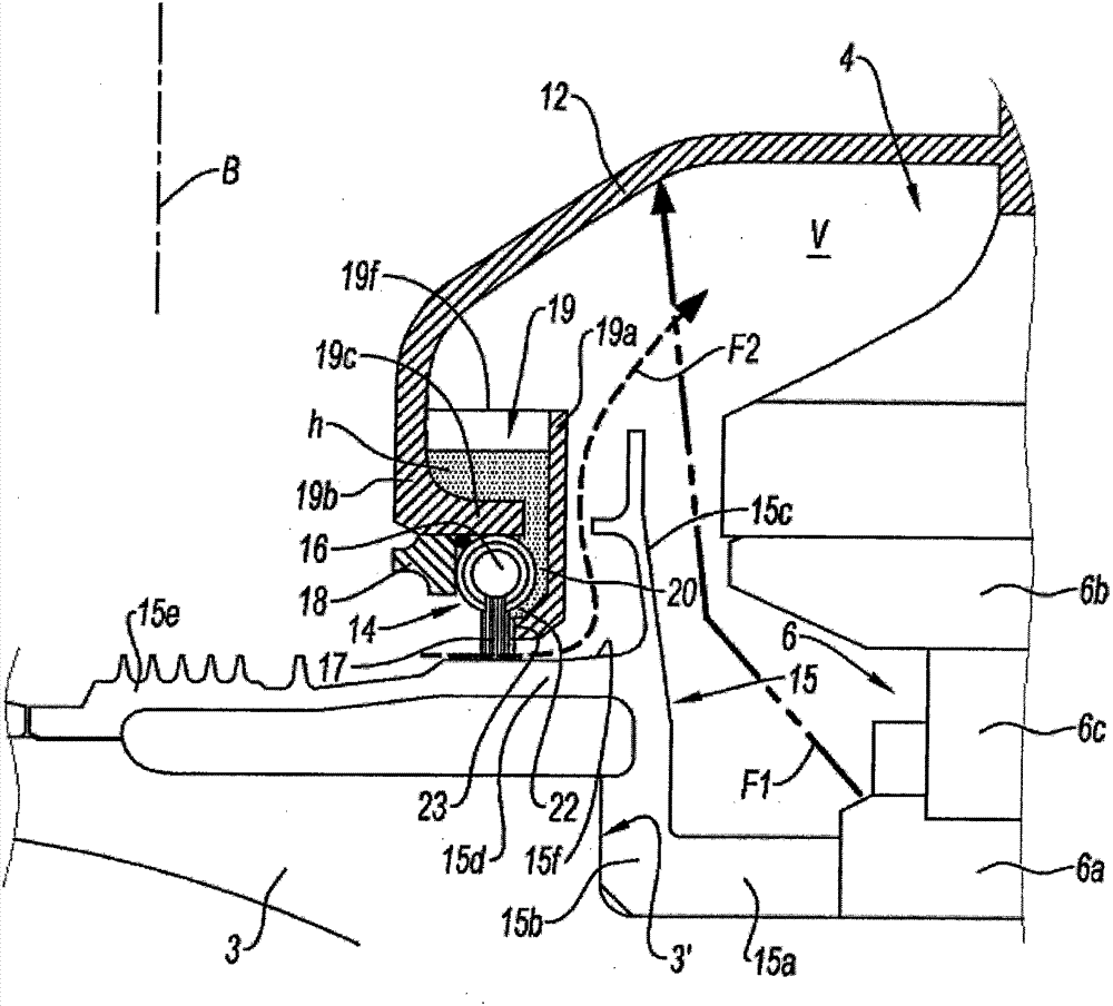
[0034] The turbojet engine 1 has an "upstream oil casing" 4 near the upstream end of the high pressure core, containing bearings and gear components, and a "downstream oil casing" 5, containing bearings and gear components, ne...


PUM


Abstract

The invention relates to a sealing device for a chamber (4, 5) that is formed of at least one rotary member (3, 15) and at least one static member (12, 13) of a jet engine (1) and is intended to contain a lubricating oil droplet suspension (h). The sealing device comprises at least one brush seal (14) that has juxtaposed strands (17) and is set up so as to ensure sealing between at least one rotary member (15) and at least one stationary member (12). Said device is characterized in that it comprises a means (12, 19, 25, 30) for recovering part of the oil suspended within the inner space (V) of the chamber (4, 5) and comprises a means (20, 22, 23, 24, 26) for delivering said recovered oil (h), said delivery means being set up so as to generate a flow of oil (h) along the strands (17) of said brush seal (14), said oil flow being oriented in the direction of the rotary member (3, 15). The brush seal (14) thus provides better resistance to coking.

Description

technical field [0001] The present invention relates to a turbojet engine and in particular to a sealing arrangement for an oil enclosure of a turbojet engine. Background technique [0002] Arranged in the direction of gas flow, an aircraft turboshaft engine typically includes: a fan, one or more compressor stages (e.g., a low-pressure compressor and a high-pressure compressor), a combustor, one or more turbine stages (e.g., a high-pressure turbine and a low-pressure turbo) and exhaust nozzles. Each compressor can be connected to a turbine, and the two components are connected by a shaft, thus forming a high-pressure core and a low-pressure core. [0003] Turbojet engines generally have an "upstream enclosure" generally around the upstream end of the high pressure core, which houses the bearings and gear components. Turbojet engines generally also generally have a "downstream enclosure" around the high pressure core downstream, within which oil lubricated bearings and gear...

Claims


Application Information

Patent Timeline
Patent Type & Authority Applications(China)
IPC IPC(8): F01D11/00F01D25/18F16J15/32
CPCF01D25/183F05B2240/571F05D2240/56F01D11/001F16J15/162F16J15/3288
Inventor 杰拉德·飞利浦·高蒂尔瑟奇·雷内·莫瑞勒
Owner SN DETUDE & DE CONSTR DE MOTEURS DAVIATION S N E C M A
Why Eureka
Try Eureka