Corrugated pipe type energy accumulator

A bellows and accumulator technology, applied in actuator accumulators, fluid pressure actuating devices, mechanical equipment, etc., can solve problems such as rapid collision between pistons and limit sleeves

Active Publication Date: 2021-02-05
JAPHL POWERTRAIN SYST
View PDF13 Cites 0 Cited by
  • Summary
  • Abstract
  • Description
  • Claims
  • Application Information

AI Technical Summary

Problems solved by technology

[0003] The technical problem to be solved by the present invention is: for the bellows piston accumulator in the prior art, the rapid collision between the piston and the limit sleeve during the liquid discharge stage The problem is to provide a new bellows accumulator structure, reduce the upward movement speed of the piston, and avoid the rapid collision between the piston and the sleeve, which will cause deformation or damage to the bellows accumulator of the piston and sleeve

Method used


Image

  • Corrugated pipe type energy accumulator
  • Corrugated pipe type energy accumulator

Examples


Embodiment Construction

[0021] Below with reference to the accompanying drawings, through the description of the embodiments, the specific embodiments of the present invention, such as the shape, structure, mutual position and connection relationship between the various parts, the role and working principle of the various parts, etc., will be further described. Detailed instructions:

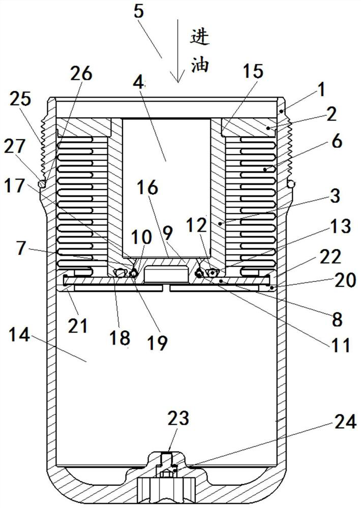
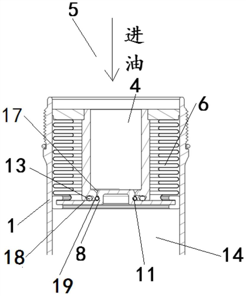
[0022] as attached figure 1 , attached figure 2 As shown, the present invention is a bellows accumulator, the inside of the tank body 1 is provided with a cover plate 2 close to the upper end, the upper end of the casing 3 is connected to the cover plate 2, the inside of the casing 3 is an oil chamber 4, and the oil chamber 4 is connected to the main oil The channel 5 is connected, the sleeve 3 is equipped with a bellows 6, the bottom of the sleeve 3 is provided with a through hole 7, the tank body 1 below the sleeve 3 is provided with a piston 8, and the protrusion 9 on the upper surface of the piston 8 is set to be...


PUM


Abstract

The invention provides a corrugated pipe type energy accumulator applied to the technical field of automobile gearboxes. The corrugated pipe type energy accumulator is characterized in that the upperend of a sleeve (3) of the corrugated pipe type energy accumulator is connected with a cover plate (2), an oil cavity (4) is formed inside the sleeve (3), a through hole (7) is formed in the bottom ofthe sleeve (3), a piston (8) is arranged below the sleeve (3), a protrusion (9) on the upper surface of the piston (8) is arranged to be a structure capable of extending into a through hole (7) of the sleeve (3), a sealing ring I (11) is arranged at the outer ring of the protrusion (9) in a sleeving mode, a sealing ring II (13) is clamped to the end face of the end, close to the piston (8), of the sleeve (3), the upper end of a corrugated pipe (6) is connected with the cover plate (2), the lower end of the corrugated pipe (6) is connected with the piston (8), and an air cavity (14) is formedinside a tank body (1) below the piston (8). According to the corrugated pipe type energy accumulator, the upward moving speed of the piston is reduced, the situation that the piston and the sleeve deform or are damaged due to rapid collision of the piston and the sleeve is avoided, and the use safety performance is improved.

Description

technical field [0001] The invention belongs to the technical field of automobile gearboxes, and more specifically relates to a bellows accumulator. Background technique [0002] The bellows accumulator commonly used today is a hydraulic energy storage device. Its working principle is: the bellows separates the tank body into two chambers - air chamber and oil chamber, the air chamber is pre-filled with a certain pressure gas, and the oil chamber communicates with the hydraulic oil circuit through the opening of the tank body. When the system oil pressure rises, the hydraulic oil pushes the piston to move downward to compress the gas (and drives the bellows to extend downward), and the pressure in the air cavity rises. When the gas pressure and the system oil pressure are balanced, the piston stops moving, and the accumulator The liquid filling stage is completed; when the oil pressure of the system decreases, the gas pressure is higher than the oil pressure, the gas pushes...

Claims


Application Information

Patent Timeline
Patent Type & Authority Applications(China)
IPC IPC(8): F15B1/24
CPCF15B1/24F15B2201/205F15B2201/31F15B2201/405
Inventor 杨培范礼丁万龙杨卫华
Owner JAPHL POWERTRAIN SYST
Why Eureka
Try Eureka