Standard test model generation method and device and storage medium
A standard testing, model generation technique
- Summary
- Abstract
- Description
- Claims
- Application Information
AI Technical Summary
Problems solved by technology
Method used
Image
Examples
Embodiment 1
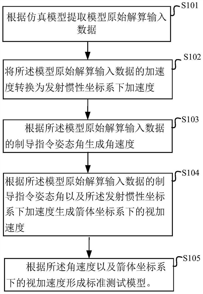
[0029] figure 1 A flow chart of steps of a method for generating a standard test model according to an embodiment of the present application is shown in FIG.
[0030] Such as figure 1 As shown, the standard test model generation method in this embodiment specifically includes the following steps:
[0031] S101, extracting model original solution input data according to the simulation model.
[0032] S102. Convert the acceleration of the input data of the original calculation of the model into the acceleration in the launching inertial coordinate system.
[0033] S103, generating an angular velocity based on the guidance instruction attitude angle of the input data from the original solution of the model.
[0034] S104. Generate the apparent acceleration in the rocket body coordinate system according to the guidance command attitude angle of the input data and the acceleration in the launching inertial coordinate system according to the original solution of the model.
[00...
Embodiment 2
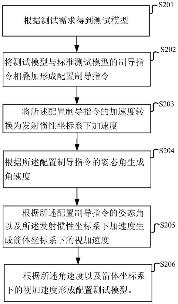
[0062] image 3 A flow chart of steps of a method for generating a standard test model according to another embodiment of the present application is shown in FIG.
[0063] Such as image 3 As shown, the standard model generation method for configuring the test requirements based on the standard test model generation further includes the following steps:
[0064] S201. Obtain a test model according to a test requirement.
[0065] S202. Superimpose the guidance instructions of the test model and the standard test model to form a configuration guidance instruction.
[0066] S203. Convert the acceleration of the configured guidance command into the acceleration in the launching inertial coordinate system.
[0067] S204. Generate an angular velocity according to the attitude angle of the configuration guidance instruction.
[0068] S205. Generate the apparent acceleration in the rocket body coordinate system according to the attitude angle of the configuration guidance command ...
Embodiment 3
[0074] In Example 3, the air rudder polarity test is configured as an example for illustration. The configuration process is as follows:
[0075] First, according to the requirements of the polarity test of the controller, a polarity test model is formed. In this embodiment, the polarity test model is the air rudder polarity test;
[0076] Specifically, the air rudder polarity test usually introduces three-channel angle deviation curves, such as pitch angle deviation curves.
[0077] Figure 4 shows the pitch angle deviation curve of the standard test model configuration method according to another embodiment of the present application.
[0078] Such as Figure 4 As shown, the deviation curve usually uses a sine wave, taking a 15°, 0.02HZ sine curve as an example.
[0079] Next, configure the air rudder polarity test.
[0080] Specifically, the air rudder polarity test inputs the specified angular deviation command to the control system, and the control system generates a ...
PUM
 Abstract
Description
Claims
Application Information
 - R&D
- Intellectual Property
- Life Sciences
- Materials
- Tech Scout
- Unparalleled Data Quality
- Higher Quality Content
- 60% Fewer Hallucinations
Browse by: Latest US Patents, China's latest patents, Technical Efficacy Thesaurus, Application Domain, Technology Topic, Popular Technical Reports.
© 2025 PatSnap. All rights reserved.Legal|Privacy policy|Modern Slavery Act Transparency Statement|Sitemap|About US| Contact US: help@patsnap.com


