Communication cable separation and recovery device

A technology of separation and recovery, recovery device, applied in the direction of recycling technology, electronic waste recycling, electrical components, etc., can solve the problems of burning, skin adhesion, incomplete peeling, etc.

Inactive Publication Date: 2021-02-05
孙玲
View PDF0 Cites 1 Cited by
  • Summary
  • Abstract
  • Description
  • Claims
  • Application Information

AI Technical Summary

Problems solved by technology

[0003] Cables will be burned, broken, and damaged during daily use. The rubber sheaths and internal copper wires on the outside of many cables can be reused. When recycling, the outer skin and inner core need to be separated. The existing separation device When separating the outer skin from the inner core, the cutting

Method used


Image

  • Communication cable separation and recovery device
  • Communication cable separation and recovery device
  • Communication cable separation and recovery device

Examples


Embodiment 1

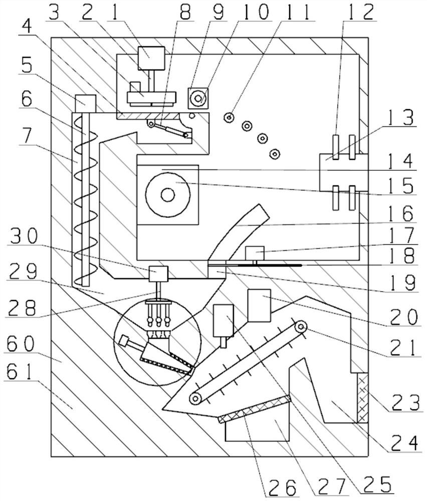
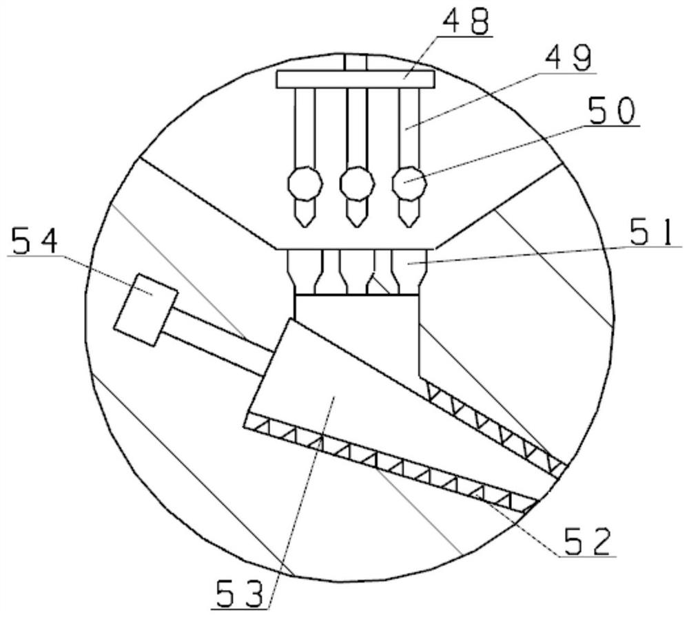
[0025] see Figure 1~Figure 6 As shown, a communication cable separation and recovery device includes a recovery device 60, and the recovery device 60 includes a box body 61, and the box body 61 is connected to a stripping device 13 through a connecting plate 12, and the stripping device 13 It includes a housing 31, a linear cylinder 62 is arranged inside the housing 31, a first motor 45 is fixedly installed on the inner wall of the housing 31, the output shaft of the first motor 45 is connected with a first gear 43, and the first The gear 43 is connected with the second gear 47 through the ring gear 32, the ring gear 32 is connected with the limit frame 46 fixedly connected with the housing 31, and the first gear 43 and the second gear 47 are equipped with a threaded shaft 41 , the threaded shaft 41 is threadedly connected with a moving sleeve 42, the moving sleeve 42 is slidably connected with a fixed frame 34, one end of the fixed frame 34 is connected with a fixed cylinder...

Embodiment 2

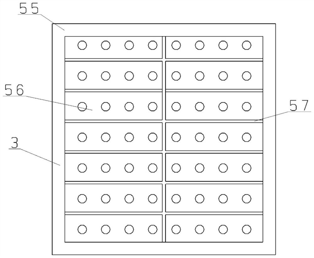
[0033] On the basis of embodiment one, refer to figure 1 , image 3 , Figure 4 , the press cutter 3 includes a knife rest 55, the knife rest 55 is provided with a recoil air pump 58 communicating with the lower chamber of the knife rest 55, an orifice 56 is arranged under the knife rest 55, and the hole A cross knife 57 is arranged under the plate 56; when the cut skin is stuck on the cross knife 57, the recoil air pump 58 inflates into the pressure cutter 3, and the high-speed air flow passes through the orifice plate 56, and the skin stuck on the cross knife 57 Blow down to prevent the cross knife 57 from being stuck by the outer skin.

[0034] Working principle: In the process of use, when using the device, the inner core is connected to the take-up roller 15, the upper layer of skin is under the pressure cutter 3, the lower layer of skin enters the conduit 16, and the device is started, driven by the second motor 14 , the inner core pulls the cable to move, while the o...


PUM


Abstract

The invention relates to the technical field of communication cable separation and recovery processing, in particular to a communication cable separation and recovery device which comprises a recoverydevice. The recovery device comprises a box body, the box body is connected with a wire stripping device through a connecting plate, and a second motor is arranged in the middle of the box body. An output shaft of the second motor is connected with a take-up roller, a guide pipe is arranged in the box body, and the guide pipe is connected with a cutting cavity. A blade is arranged in the cuttingcavity, a third motor is arranged in the box body, and an output shaft of the third motor is fixedly connected with the blade. The cutting cavity is connected with an inclined hopper cavity, the inclined hopper cavity is connected with a conveying pipe cavity, and a guide roller is arranged in the box body. A first hydraulic cylinder is installed at the upper left portion of the box body and is connected with a pressing and cutting knife through a first hydraulic rod. The communication cable separation and recovery device is sufficient in cutting depth, skin is not prone to adhesion, peeling is complete, crushing and recycling treatment is achieved, and transportation and follow-up processing treatment are facilitated.

Description

technical field [0001] The invention relates to the technical field of separation and recycling of communication cables, in particular to a device for separating and recycling communication cables. Background technique [0002] Communication cables are cables that transmit telephone calls, telegrams, fax documents, TV and radio programs, data and other electrical signals. Twisted by more than one pair of mutually insulated wires, the communication cable has the advantages of large communication capacity, high transmission stability, good confidentiality, and less affected by natural conditions and external interference compared with overhead open wires. [0003] Cables will be burned, broken, and damaged during daily use. The rubber sheaths and internal copper wires on the outside of many cables can be reused. When recycling, the outer skin and inner core need to be separated. The existing separation device When separating the outer skin from the inner core, the cutting dep...

Claims


Application Information

Patent Timeline
IPC IPC(8): H01B15/00
CPCH01B15/006H01B15/008Y02W30/82
Inventor 孙玲
Owner 孙玲
Why Eureka
Try Eureka