Energy-saving and environment-friendly power distribution cabinet capable of dissipating heat

An energy-saving, environmentally friendly and heat-dissipating technology, applied in substation/distribution device housing, electrical components, substation/switch layout details, etc.

Inactive Publication Date: 2021-02-05
广州腾涟晟建材有限公司
View PDF0 Cites 0 Cited by
  • Summary
  • Abstract
  • Description
  • Claims
  • Application Information

AI Technical Summary

Problems solved by technology

[0005] In order to overcome the shortcomings of the existing power distribution cabinets, which cannot dissipate heat, easily accumulate dust, and affect the appearance, the technical problem to be solved is to provide an energy-saving device that can independently dissipate heat, automatically scrape off dust and reset, and prevent damage to components during the scraping process. Environmentally friendly heat dissipation power distribution cabinet

Method used


Image

  • Energy-saving and environment-friendly power distribution cabinet capable of dissipating heat
  • Energy-saving and environment-friendly power distribution cabinet capable of dissipating heat
  • Energy-saving and environment-friendly power distribution cabinet capable of dissipating heat

Examples


Embodiment 1

[0033]An energy-saving and environment-friendly heat-dissipating power distribution cabinet, such asfigure 1 ,figure 2 ,image 3 withFigure 4 As shown, it includes a supporting leg 1, a housing 2, a rotating door 21, a handle 22, an energy component 3, and a fan assembly 4. There are four supporting legs 1, and two supporting legs 1 are symmetrically distributed on the front side. There are also two supporting feet 1 symmetrically distributed left and right. A housing 2 is connected between the upper sides of the supporting feet 1, a rotating door 21 is rotatably connected to the left front side of the housing 2, and a handle 22 is connected to the middle of the right front of the rotating door 21. The housing 2 is provided with an energy component 3 inside, and the lower part and the left and right sides of the housing 2 are provided with fan components 4.

[0034]The energy component 3 includes a solar panel 31, a duct 32, a ball 33, a first push rod 34, and a button 35. The upper sid...

Embodiment 2

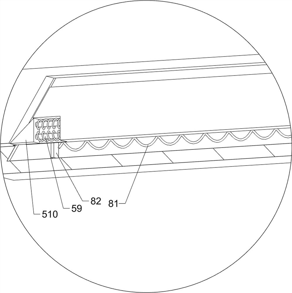
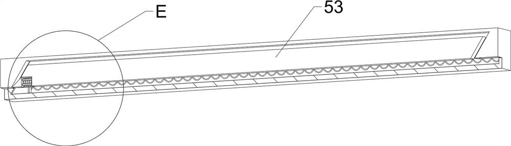
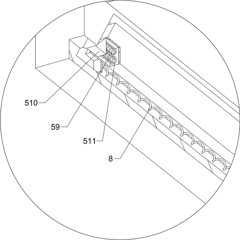
[0038]On the basis of Example 1, such asFigure 5 ,Image 6 ,Figure 7 ,Figure 8 ,Picture 9 ,Picture 10 withPicture 11As shown, the ash scraper assembly 5 is also included. The ash scraper assembly 5 includes a worm 51, a transmission assembly 52, a sliding rail 53, a first spring 54, a first scraper 55, a connecting rod 56, a second push rod 57, and a The three push rod 58, the first guide rod 59, the first wedge block 510 and the second spring 511, a worm 51 is rotatably connected between the lower left side of the lower part of the housing 2 and the lower right side of the support foot 1, and the upper right side A transmission assembly 52 is connected between the drive shaft of the fan blade 44 and the right side of the worm 51, a slide rail 53 is connected to the front side of the bottom of the housing 2, and a connecting rod 56 is slidably connected inside the slide rail 53. The rear side of the connecting rod 56 slides with the worm 51 The middle part of the connecting rod 56 is...


PUM


Abstract

The invention relates to a power distribution cabinet, in particular to an energy-saving and environment-friendly power distribution cabinet capable of dissipating heat. The technical problem to be solved is to provide an energy-saving and environment-friendly power distribution cabinet capable of automatically dissipating heat, automatically scraping dust and resetting, and preventing componentsfrom being damaged in the dust scraping process. The energy-saving and environment-friendly power distribution cabinet capable of dissipating heat comprises: four supporting legs; a shell which is connected between the upper parts of the supporting legs; a rotary door which is rotationally connected to one side of the shell; a handle which is connected to the middle of one side of the rotary door;an energy assembly which is arranged between the upper part and the inner part of the shell; and a fan assembly which is arranged between the lower portion and the two sides of the shell. The front side of the connecting rod moves leftwards to push the push plate to move leftwards, and the sixth spring is gradually compressed, so that a buffer effect is provided for resetting movement of the connecting rod, and the connecting rod is prevented from being damaged due to high-speed resetting movement.

Description

Technical field[0001]The invention relates to a power distribution cabinet, in particular to an energy-saving and environmentally-friendly radiating power distribution cabinet.Background technique[0002]The power distribution cabinet is the general name of the motor control center. It is mainly used to provide protection, monitoring and control to the load, allowing users to see the operating status of the power distribution system in the computer room at a glance, so as to find safety hazards and avoid risks early.[0003]Due to the characteristics of the power distribution cabinet itself, the internal circuits are dense, which often increases the internal temperature of the power distribution cabinet during use. The traditional power distribution cabinet lacks heat dissipation facilities, which makes the power distribution cabinet stay in a high temperature state for a long time, which easily affects the distribution motor The normal operation of the power distribution cabinet has po...

Claims


Application Information

Patent Timeline
Patent Type & Authority Applications(China)
IPC IPC(8): H02B1/56H02B1/30H02B1/28H02B1/32
CPCH02B1/28H02B1/30H02B1/32H02B1/565
Inventor 廖美华
Owner 广州腾涟晟建材有限公司
Why Eureka
Try Eureka