Motor capable of quickly stopping

A fast, chassis-based technology, applied in the direction of electromechanical devices, electrical components, and electric components, can solve the problems of low motor operation efficiency, affecting the normal use of the motor, and reducing the damping torque, so as to avoid the load slipping or slipping, and meet the long-term requirements. The effect of stable operation over time and stable output damping torque

Pending Publication Date: 2021-02-05
HENGDIAN GRP INNUOVO ELECTRIC
View PDF1 Cites 1 Cited by
  • Summary
  • Abstract
  • Description
  • Claims
  • Application Information

AI Technical Summary

Problems solved by technology

The above solution has the following defects: ① When mechanical parts such as compression springs rotate, noise will be generated, and parts such as compression springs will wear out, generating debris and dust, and there is a risk of motor parts getting stuck and shortening the service life; ② With Due to the wear of parts such as compression springs, the damping torque will gradually decrease with the increase of use time, and it is difficult to achieve a fast stop after the motor is powered off; ③This mechanical resistance structure will affect the normal use of the motor, and the motor will Loss of mechanical power, the motor operates less efficiently

Method used


Image

  • Motor capable of quickly stopping
  • Motor capable of quickly stopping
  • Motor capable of quickly stopping

Examples


Embodiment 1

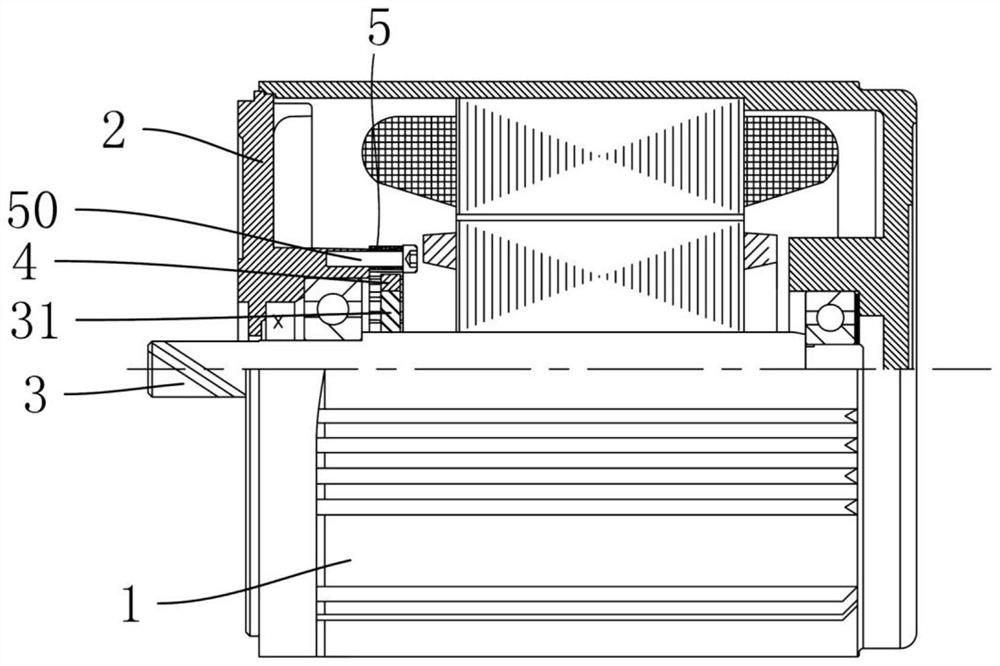
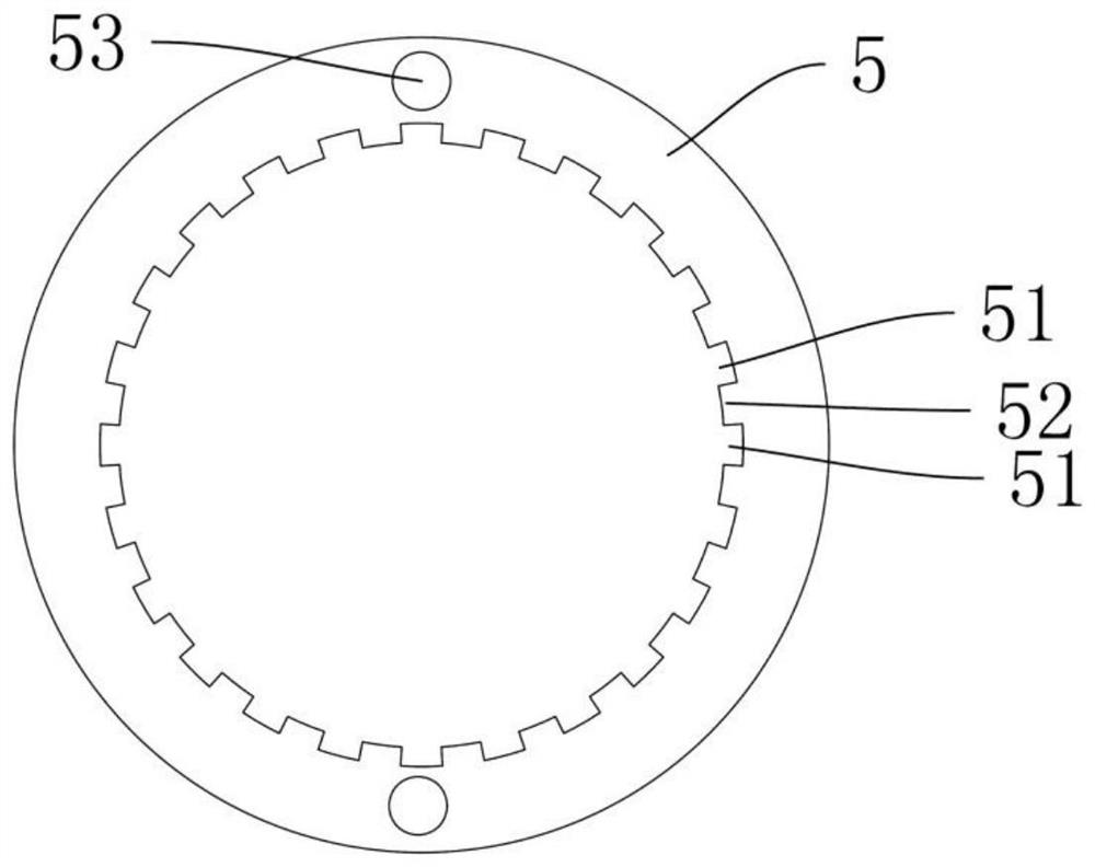
[0027] Depend on figure 1 with figure 2 As shown, a motor that can be stopped quickly includes a casing 1, an end cover 2, a rotor, a magnetic ring 4 and a metal ring 5, the metal ring 5 is made of magnetically conductive material, the magnetic ring 4 is a permanent magnet, and the magnetic ring 4 The metal ring 5 is adjacent to each other and can interact with each other with magnetic force. The metal ring 5 is provided with a plurality of grooves 51 on the end surface or the circumferential surface adjacent to the magnetic ring 4. The plurality of grooves 51 are arranged at uniform intervals in a circular shape in the circumferential direction of the metal ring. A number of magnetic poles are formed on the end face or circumferential surface adjacent to the ring 4 and the metal ring 5. The number of grooves 51 is the same as the number of magnetic poles of the magnetic ring 4, and the magnetic poles are alternately arranged in N poles and S poles in the circumferential dire...

Embodiment 2

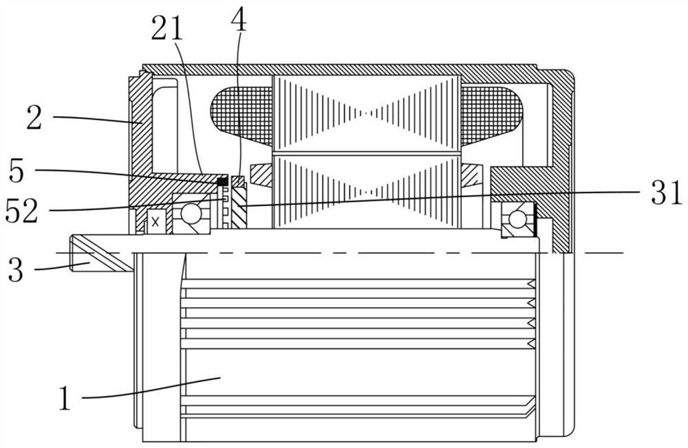
[0032] Depend on image 3 with Figure 4 As shown, the difference between this embodiment and Embodiment 1 is that: the magnetic ring 4 and the metal ring 5 are arranged at intervals along the axial direction of the rotor, the magnetic poles are formed on the end surface of the magnetic ring 4, and the metal ring is provided with The groove 51 on the surface, the end surface of the magnetic ring 4 and the end surface of the metal ring 5 have a ring-shaped overlapping surface along the rotor axial direction. The inner side of the end cover 2 is formed with a fixing groove, the metal ring 5 is fixed in the fixing groove, the fixing groove is located at the opening of the bearing bracket 21 of the end cover 2, and the metal ring 5 is fixed in the fixing groove by die-casting.

Embodiment 3

[0034] Depend on Figure 5 with Image 6 As shown, the difference between this embodiment and Embodiment 1 is that the axis of the metal ring 5 deviates from the axis of the magnetic ring 4 . Wherein, the connecting ring 31 has a stepped structure, the rotor shaft 3 has a stepped protrusion 30 for limiting the connecting ring 31 , the connecting ring 31 is tightly fitted on the rotor shaft, and the magnetic ring 4 is tightly fitted on the connecting ring 31 . The inner side of the end cover 2 is formed with a fixing groove, the metal ring 5 is fixed in the fixing groove, the fixing groove is located at the opening of the bearing bracket 21 of the end cover 2, and the metal ring 5 is fixed in the fixing groove by die-casting.

[0035] When the motor of the present invention is in normal use, the damping torque between the metal ring and the magnetic ring alternates between positive and negative at different times, so that the rotor is continuously subjected to alternate pullin...


PUM


Abstract

The invention relates to a motor, and concretely relates to a motor capable of rapidly stopping. The motor capable of rapidly stopping comprises a casing, an end cover, a rotor, a magnetic ring and ametal ring, the metal ring is made of a magnetic conductive material, the magnetic ring and the metal ring are close to each other and can generate magnetic force mutually, and a plurality of groovesare formed in the end face or the circumferential face, close to the magnetic ring, of the metal ring. A plurality of grooves are formed in the metal ring and annularly arranged at intervals in the circumferential direction of the metal ring, a plurality of magnetic poles are formed on the end face or the circumferential face, adjacent to the metal ring, of the magnetic ring, the number of the grooves is the approximate number or multiple of the number of the magnetic poles of the magnetic ring, and the magnetic poles are arranged in an N-pole and S-pole staggered mode in the circumferential direction of the magnetic ring. One of the two annular pieces of the magnetic ring and the metal ring is coaxially fixed with the rotor, and the other one of the two annular pieces is fixed with the casing or the end cover. Compared with a motor using a conventional mechanical damping structure, the motor provided by the invention is higher in efficiency during normal operation.

Description

technical field [0001] The invention relates to a motor, in particular to a motor that can be stopped quickly. Background technique [0002] The Chinese patent with the application number 201910494172.1 discloses a motor that can be stopped quickly. The rotor shaft is damped by a mechanical structure such as a compression spring to further reduce the speed of the rotor after the motor is powered off, so as to realize the rapid stop of the rotor. Realize the rapid shutdown of the motor. The above solution has the following defects: ① When mechanical parts such as compression springs rotate, noise will be generated, and parts such as compression springs will wear out, generating debris and dust, and there is a risk of motor parts getting stuck and shortening the service life; ② With Due to the wear of parts such as compression springs, the damping torque will gradually decrease with the increase of use time, and it is difficult to achieve a fast stop after the motor is powere...

Claims


Application Information

Patent Timeline
Patent Type & Authority Applications(China)
IPC IPC(8): H02K7/10H02K7/106
CPCH02K7/10H02K7/106
Inventor 魏中华朱智平张磊任凯乐朱雨剑
Owner HENGDIAN GRP INNUOVO ELECTRIC
Why Eureka
Try Eureka