Automatic blockage-clearing waste gas filtering device and method
A waste gas filtration and automatic cleaning technology, which is applied in separation methods, dispersed particle filtration, chemical instruments and methods, etc., can solve the problems of low filtration efficiency and failure, and achieve the effect of enhancing filtration efficiency and avoiding substandard emissions
- Summary
- Abstract
- Description
- Claims
- Application Information
AI Technical Summary
Problems solved by technology
Method used
Image
Examples
Embodiment 1
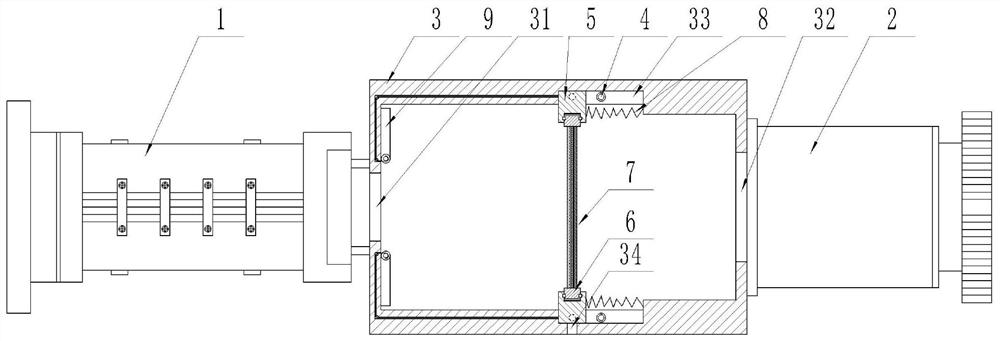
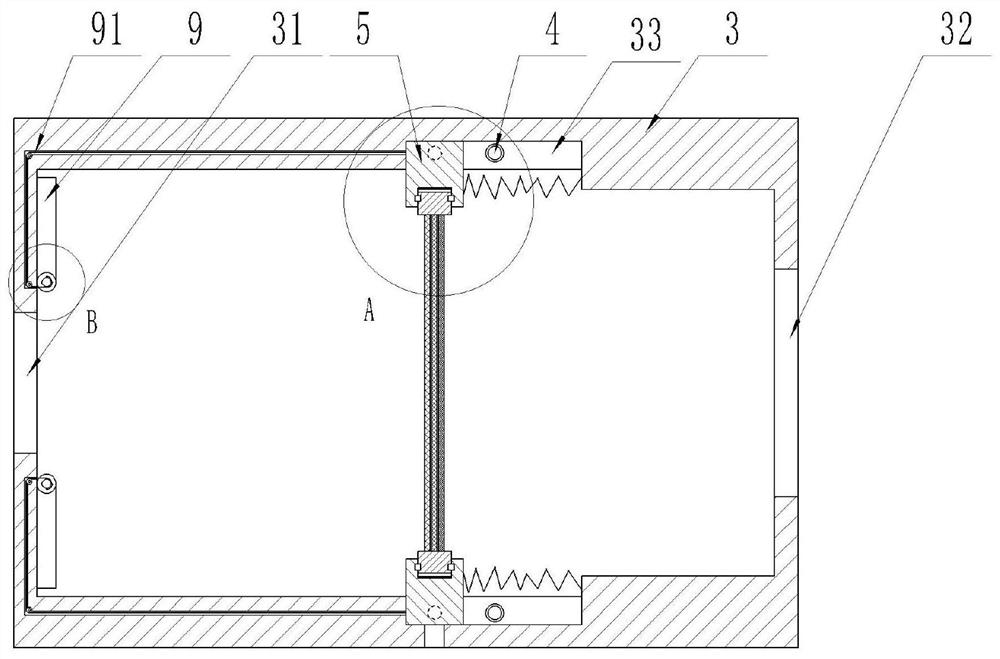
[0057] An automatic declogging waste gas filter device, such as figure 1 , 2 As shown, it includes an intake pipeline 1 and a purification pipeline 2, wherein the intake pipeline 1 and the purification pipeline 2 communicate with the cleaning filter mechanism 3, and the cleaning filter mechanism 3 includes: an air inlet 31, an air outlet 32, and a chute 33. Vibration head 4, sliding block 5, negative pressure port 34, connecting ring 6, filter unit 7, sealing plate 9.
[0058] The intake pipe 1 is provided with a suction mechanism for attracting exhaust gas, the air inlet 31 is connected to one end of the intake pipe 1, the other end of the intake pipe 1 is connected to the exhaust gas spray tower (not shown), and the air outlet 32 is connected to the purification Pipeline 2, after the clean gas pipeline, the gas can be measured, if it meets the emission standard, it can be discharged, if it still does not meet the emission standard, the next step of cleaning can be carried...
Embodiment 2
[0072] An automatic declogging waste gas filtering device has the same characteristic structure as that of Embodiment 1, wherein, such as Figure 7 As shown, the cleaning filter mechanism 3 also includes: a trigger lever 20 , a pressure spring 21 , a blocking plate 22 , and an air pressure tube 30 .
[0073] The trigger lever 20 is arranged at the right end position of the chute 33 , and the trigger lever 20 is provided with a pressure spring 21 . Blocking plate 22 links to each other with the right end of trigger lever 20, and blocking plate 22 passes through the air pressure block, and blocking plate 22 is used for blocking off the communication of air pressure pipe 30 and the space where filter unit 7 is located, and there is a pair on the left side of blocking plate 22. The interface 23 is used to communicate with the air pressure tube 30 after the blocking plate 22 moves to the right. The pneumatic tube 30 has a pneumatic head towards the filter unit 7 .
[0074] Such a...
Embodiment 3
[0076] An automatic plugging method, wherein, comprising the following steps:
[0077] The exhaust gas is introduced into the clean filter mechanism 3 through the intake pipeline 1, and after the exhaust gas enters from the air inlet 31 of the clean filter mechanism 3, the particulate matter in the exhaust gas is filtered through the filter unit 7;
[0078] When the filter unit 7 has filtered and accumulated a large amount of particles for a long time, the exhaust gas is difficult to be filtered by the filter unit 7, and the filter unit 7 is under the pressure of the exhaust gas, pushing the connecting ring 6 and the sliding block 5 connected with the connecting ring 6 to the right along the chute 33 Sliding, sliding block 5 makes negative pressure port 34 open, and is no longer blocked by sliding block 5, and the sliding pull stay cord 91 of sliding block 5 moves simultaneously, makes the sealing plate 9 rotations of air inlet 31 places, and air inlet 31 for sealing;
[0079...
PUM
 Abstract
Description
Claims
Application Information
 - R&D
- Intellectual Property
- Life Sciences
- Materials
- Tech Scout
- Unparalleled Data Quality
- Higher Quality Content
- 60% Fewer Hallucinations
Browse by: Latest US Patents, China's latest patents, Technical Efficacy Thesaurus, Application Domain, Technology Topic, Popular Technical Reports.
© 2025 PatSnap. All rights reserved.Legal|Privacy policy|Modern Slavery Act Transparency Statement|Sitemap|About US| Contact US: help@patsnap.com


