Self-centering lathe center frame

A center frame, self-centering technology, applied in the direction of large fixed members, metal processing machinery parts, metal processing equipment, etc., can solve the problems of difficult installation of machine tools, troublesome workpiece adjustment, small clamping range, etc., to achieve good performance, The effect of saving time for loading and unloading workpieces and increasing the clamping range

Pending Publication Date: 2021-02-09
宁波市精恒凯翔机械有限公司
View PDF0 Cites 1 Cited by
  • Summary
  • Abstract
  • Description
  • Claims
  • Application Information

AI Technical Summary

Problems solved by technology

In the prior art, the mechanical three-jaw transfer center frame is commonly used on lathes. This type of center frame is not only troublesome to adjust the

Method used


Image

  • Self-centering lathe center frame
  • Self-centering lathe center frame
  • Self-centering lathe center frame

Examples


Embodiment Construction

[0024] Embodiments of the present invention will be described in further detail below in conjunction with the accompanying drawings.

[0025] Figures 1 to 9 It is the schematic diagram of construction and wall pile of the present invention.

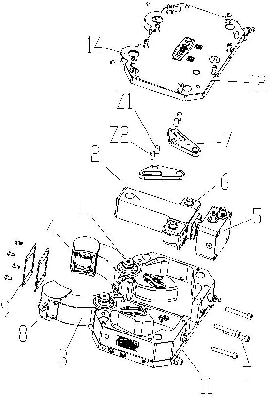
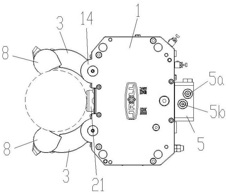
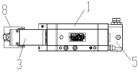
[0026] The reference signs are: rotating shaft L, connecting bolt T, first pin Z1, second pin Z2, shell 1, assembly cavity 1a, rear notch 1b, main shell 11, cover plate 12, right support ear 13. Left support ear 14, oil cylinder 2, center arm 21, support arm 3, arc-shaped rolling surface 3a, second slideway 31, second pin hole 32, support wheel set 4, support wheel 41, safety valve 5, Oil inlet 5a, oil outlet 5b, roller group 6, roller seat 61, roller shaft 62, roller 63, return plate 7, reaming hole 7a, first slideway 7b, first pin hole 7c, iron dust protection windshield 8. Connecting hole 8a, spray hole 8b, locking block 81, pressure plate 9.

[0027] Such as Figure 1 to Figure 9 As shown, the present invention provides a kind of...


PUM


Abstract

The invention discloses a self-centering lathe center frame. The self-centering lathe center frame comprises a shell, a center arm and two supporting arms; the front end of the center arm and the front ends of the two supporting arms are each provided with a supporting wheel set; the center arm is a cylinder body of an oil cylinder hidden in the shell, and a safety valve is assembled at the end ofa piston rod of the oil cylinder and installed on the rear end face of the shell; roller sets are symmetrically installed on the upper side face and the lower side face of the center arm, and outwards-protruding arc-shaped rolling faces in rolling contact fit with the roller sets are formed on the rear sections of the supporting arms; and the center arm moves forwards under the action of hydraulic pressure, meanwhile, the two supporting arms are pushed to synchronously move and fold through rolling force application of the roller sets to control a workpiece in a circle formed by supporting points of the three supporting wheel sets, and a return plate used for driving the supporting arms to be opened and reset when the center arm retreats is hinged to the center arm. According to the self-centering lathe center frame, by the adoption of the design of the built-in oil cylinder, the boundary dimension of the center frame is reduced, the clamping range is enlarged, reliability is high, using performance is good, and the self-centering lathe center frame is suitable for a machine tool with a small installation space and a large clamping range.

Description

technical field [0001] The invention relates to the technical field of mechanical processing equipment, in particular to a center frame applied to a lathe, in particular to a center frame of a self-centering lathe. Background technique [0002] The center frame is an auxiliary support device used in the turning or grinding process of slender shaft parts, which makes it possible for high-precision machining of ultra-thin optical shafts, precision screw rods, ball screws and other parts. In the prior art, the mechanical three-jaw transfer center rest is commonly used on lathes. This kind of center rest is not only troublesome to adjust the center of the workpiece, but also difficult to install in the space due to its large size and small clamping range. Machine tool with small clamping range. Contents of the invention [0003] The technical problem to be solved by the present invention is to provide a self-centering lathe steady rest with built-in oil cylinder design, small...

Claims


Application Information

Patent Timeline
IPC IPC(8): B23Q1/76
CPCB23Q1/763
Inventor 李龙江
Owner 宁波市精恒凯翔机械有限公司
Why Eureka
Try Eureka