Grinding device for electrical equipment production

A technology of electrical equipment and equipment, applied in the direction of grinding drive device, grinding/polishing safety device, metal processing equipment, etc., can solve the problems of not providing arc surface grinding, time-consuming and laborious work efficiency, dust collection and cleaning, etc., to avoid The effect of flying, reducing consumption and easy operation

Inactive Publication Date: 2021-02-09
德清创赢机械科技有限公司
View PDF0 Cites 0 Cited by
  • Summary
  • Abstract
  • Description
  • Claims
  • Application Information

AI Technical Summary

Problems solved by technology

[0004] (1) The existing grinding device can only complete the grinding work of a single plane surface, and does not provide the function of grinding the curved surface, so there is no problem of processing the curved surface, and according to the curvature of the curved surface, the curved surface can only be done manually grinding, time-consuming and labor-intensive and low work efficiency;
[0005] (2) Most of the dust generated by the existing grinding device during the grinding process cannot be directly collected and cleaned, and there are still devices that rely on wind to blow away waste materials. This process is likely to cause waste dust after the surface of other devices is covered, and there is no It fundamentally solves the problem of waste collection, and the cleaning device is additionally installed with corresponding control equipment, which consumes additional power resources

Method used


Image

  • Grinding device for electrical equipment production
  • Grinding device for electrical equipment production
  • Grinding device for electrical equipment production

Examples


Embodiment Construction

[0028] The following will clearly and completely describe the technical solutions in the embodiments of the present invention with reference to the accompanying drawings in the embodiments of the present invention. Obviously, the described embodiments are only some, not all, embodiments of the present invention. Based on the embodiments of the present invention, all other embodiments obtained by persons of ordinary skill in the art without making creative efforts belong to the protection scope of the present invention.

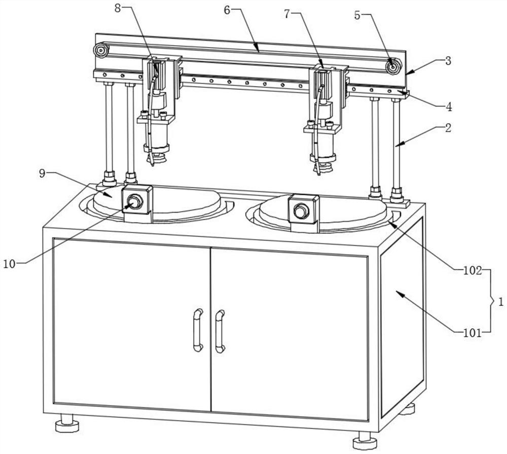
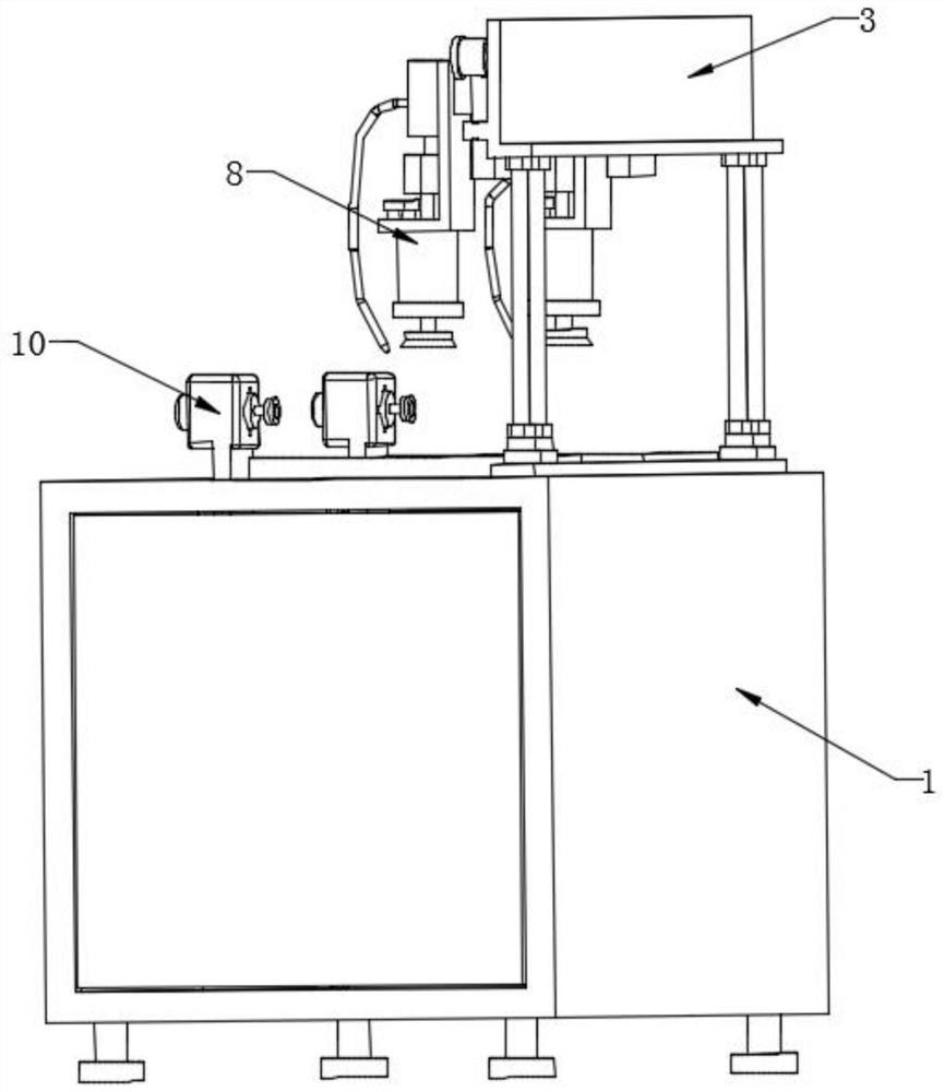
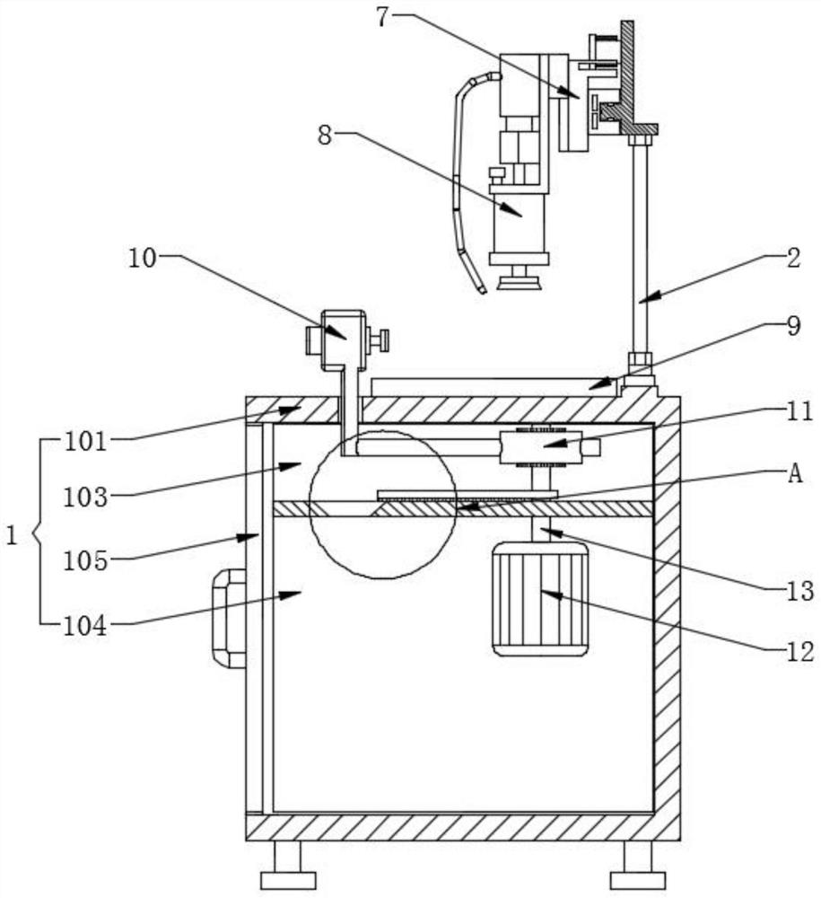
[0029] Please also refer to Figure 1-7 , figure 1 It is a front view three-dimensional structural schematic diagram of a grinding device for electrical equipment production in an embodiment of the present invention, figure 2 for figure 1 The schematic diagram of the rear view three-dimensional structure shown in the embodiment, image 3 for figure 1 The side view sectional structural schematic diagram shown in the embodiment, Figure 4 for figure 1 A s...


PUM


Abstract

The invention discloses a grinding device for electrical equipment production. The grinding device for electrical equipment production comprises a grinding machine box assembly, a movable base assembly, a grinding dust suction assembly, clamps, cambered surface grinding assemblies and an inner linkage assembly; the movable base assembly is movably arranged above the grinding machine box assembly;and the grinding dust suction assembly is movably installed on the surface of the movable base assembly; the clamps are fixedly installed on the two sides of the upper surface of the grinding machinebox assembly correspondingly; the cambered surface grinding assemblies are fixedly installed in the upper surface of the grinding machine box assembly; and the inner linkage assembly is fixedly arranged at the upper end of the interior of the grinding machine box assembly. The device can be used for jointly grinding the surfaces and arc surfaces of equipment parts, is convenient to operate and high in working efficiency, additionally an energy-saving dust suction device is provided to prevent dust from flying, finally the surface and the interior of the device are deeply cleaned, and additional circuit control is not needed.

Description

technical field [0001] The invention relates to the technical field of equipment grinding, in particular to a grinding device for electrical equipment production. Background technique [0002] Grinding is a kind of surface modification technology. It generally refers to a processing method that uses rough objects (sandpaper with higher hardness particles, etc.) to change the physical properties of the material surface through friction. The main purpose is to obtain a specific surface roughness; [0003] Yet there is following defect in existing grinding device: [0004] (1) The existing grinding device can only complete the grinding work of a single plane surface, and does not provide the function of grinding the curved surface, so there is no problem of processing the curved surface, and according to the curvature of the curved surface, the curved surface can only be done manually grinding, time-consuming and labor-intensive and low work efficiency; [0005] (2) Most of t...

Claims


Application Information

Patent Timeline
IPC IPC(8): B24B19/00B24B19/26B24B27/00B24B47/12B24B47/16B24B47/20B24B55/06B24B55/12
CPCB24B19/00B24B19/26B24B27/0076B24B47/12B24B47/16B24B47/20B24B55/06B24B55/12
Inventor 姚晓辉闻琦姚冬
Owner 德清创赢机械科技有限公司
Why Eureka
Try Eureka