
Working fluid level tester for oil production well

A technology for dynamic liquid surface and production wells, which is applied in measurement, earthwork drilling and production, wellbore/well components, etc. It can solve problems such as lack of detection curves, failure to consider the influence of oil well casing temperature, signal interference, etc.

Pending Publication Date: 2021-02-09
SINOPEC SHENGLI OILFIELD
View PDF0 Cites 0 Cited by
  • Summary
  • Abstract
  • Description
  • Claims
  • Application Information

AI Technical Summary

Problems solved by technology

[0004] 1. Traditional testing instruments do not consider the influence of oil well casing temperature, oil well casing width, and oil well casing depth on the monitoring results;
[0005] 2. Traditional testing instruments use fixed monitoring intervals, monitoring frequencies, and monitoring parameters, resulting in some errors in monitoring results, weak signals at certain positions on the moving liquid surface, missing detection curves or interference with signals The problem;

Method used


Image

  • Working fluid level tester for oil production well
  • Working fluid level tester for oil production well
  • Working fluid level tester for oil production well

Examples


Embodiment Construction

[0045] The above and other technical features and advantages of the present invention will be described in more detail below in conjunction with the accompanying drawings.

[0046] Preferred embodiments of the present invention are described below with reference to the accompanying drawings. Those skilled in the art should understand that these embodiments are only used to explain the technical principles of the present invention, and are not intended to limit the protection scope of the present invention.

[0047] It should be noted that, in the description of the present invention, terms such as "upper", "lower", "left", "right", "inner", "outer" and other indicated directions or positional relationships are based on the terms shown in the accompanying drawings. The direction or positional relationship shown is only for convenience of description, and does not indicate or imply that the device or element must have a specific orientation, be constructed and operated in a spec...


PUM


Abstract

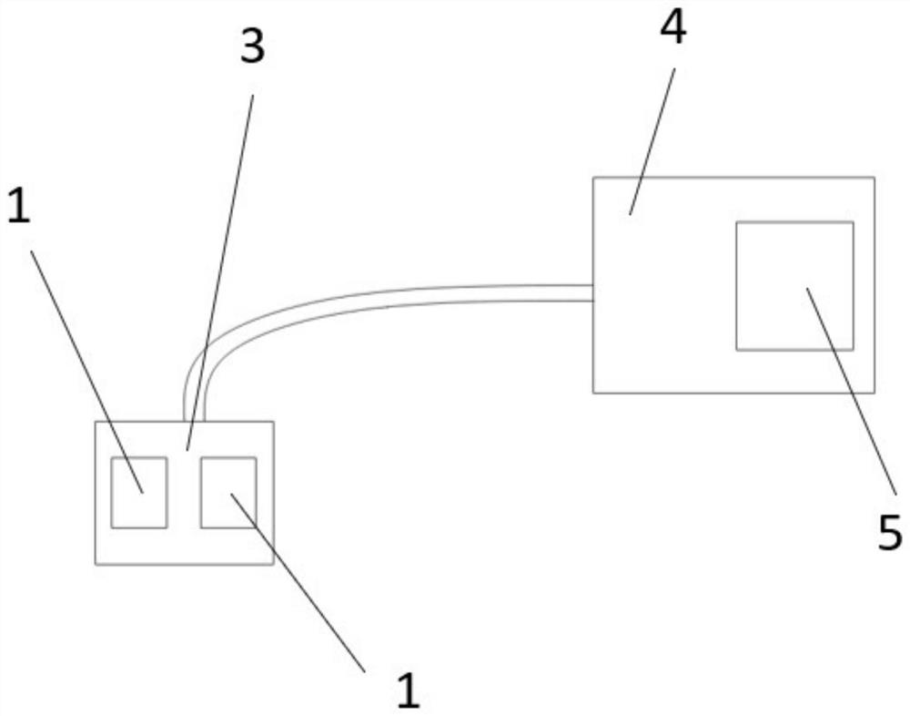
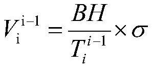
The invention relates to a working fluid level tester for an oil production well. The tester comprises an infrasonic wave generating device, an echo receiving device, a display device and a control system. The sleeve depth, the sleeve height, the mining place temperature, the crude oil viscosity and the temperature in a sleeve of a pre-detected oil well are obtained, the factors are taken into consideration, and the mining grade of the pre-detected oil well is calculated. Meanwhile, the infrasonic wave frequency and the monitoring interval of the infrasonic wave generating device are adjustedin real time by adopting different standards according to the crude oil exploitation grade, the i monitored working fluid level height Bi and the height interval where the working fluid level height Bi is located, so that the situation that the oil well to be monitored is monitored in real time at the good infrasonic wave frequency, accurate and clear feedback data are obtained, the accuracy of a monitoring result is improved, meanwhile, the monitoring interval is automatically adjusted in real time, energy is saved, and the situation that the position of the working fluid level is captured in the whole monitoring process is guaranteed.

Description

technical field [0001] The field of the invention is the field of measuring instruments, specifically a dynamic liquid level tester for oil production wells. Background technique [0002] The dynamic liquid level is the liquid level in the annular space of the tubing and the casing when the pumping well is in normal production, and this liquid level is called the dynamic liquid level. The dynamic liquid level can be expressed by the depth from the wellhead, or by the height from the middle of the oil layer. In the process of oil well production, the maximization of production and comprehensive efficiency is the ultimate goal, and the liquid supply of the formation Capacity is the fundamental factor restricting the realization of this goal. The dynamic liquid level of an oil well is an important index reflecting the liquid supply capacity of the formation, and an important basis for determining a reasonable submergence degree and formulating a reasonable working system in th...

Claims


Application Information

Patent Timeline
IPC IPC(8): E21B47/047E21B47/002E21B47/00
CPCE21B47/00
Inventor 姚秀田王雅冉贾蕾骆毅赵鑫高阳王涛马军郭其胜黄安源刘阳王冉冉
Owner SINOPEC SHENGLI OILFIELD
Learn More