
Crankshaft oil seal assembly, crankcase and vehicle

A crankcase and oil seal technology, applied in the field of vehicles, can solve the problems of seal failure, affecting the efficiency of oil seal press-fitting, factory production rhythm, and increasing manufacturing costs, and achieve the effect of avoiding deformation.

Inactive Publication Date: 2021-02-09
ZHEJIANG GEELY HLDG GRP CO LTD +2
View PDF5 Cites 0 Cited by
  • Summary
  • Abstract
  • Description
  • Claims
  • Application Information

AI Technical Summary

Problems solved by technology

[0003] However, during the press-in process of the oil seal, due to the elasticity of the rubber body, the oil seal will be deformed and tilted, resulting in seal failure. Therefore, it is necessary to use tooling and control the press-fitting speed to avoid tilting and deformation of the oil seal when it is pressed into the assembly cavity. , but it will also affect the efficiency of oil seal press-fitting and the production cycle of the factory
At the same time, when there is a dimensional deviation in the manufacturing process, which leads to insufficient interference between the oil seal and the assembly cavity, or when the processing surface of the assembly cavity is too smooth, the pull-out force of the oil seal in the assembly cavity is insufficient. When abnormally large, the oil seal is easy to come out from the assembly cavity, resulting in oil leakage
Moreover, in order to ensure that the oil seal has sufficient pull-out force, it is necessary to control the roughness range and processing method of the assembly cavity, which increases the manufacturing cost

Method used


Image

  • Crankshaft oil seal assembly, crankcase and vehicle
  • Crankshaft oil seal assembly, crankcase and vehicle
  • Crankshaft oil seal assembly, crankcase and vehicle

Examples


Embodiment Construction

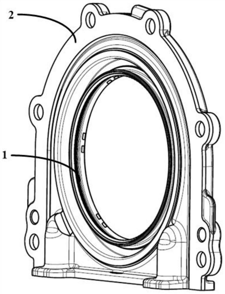
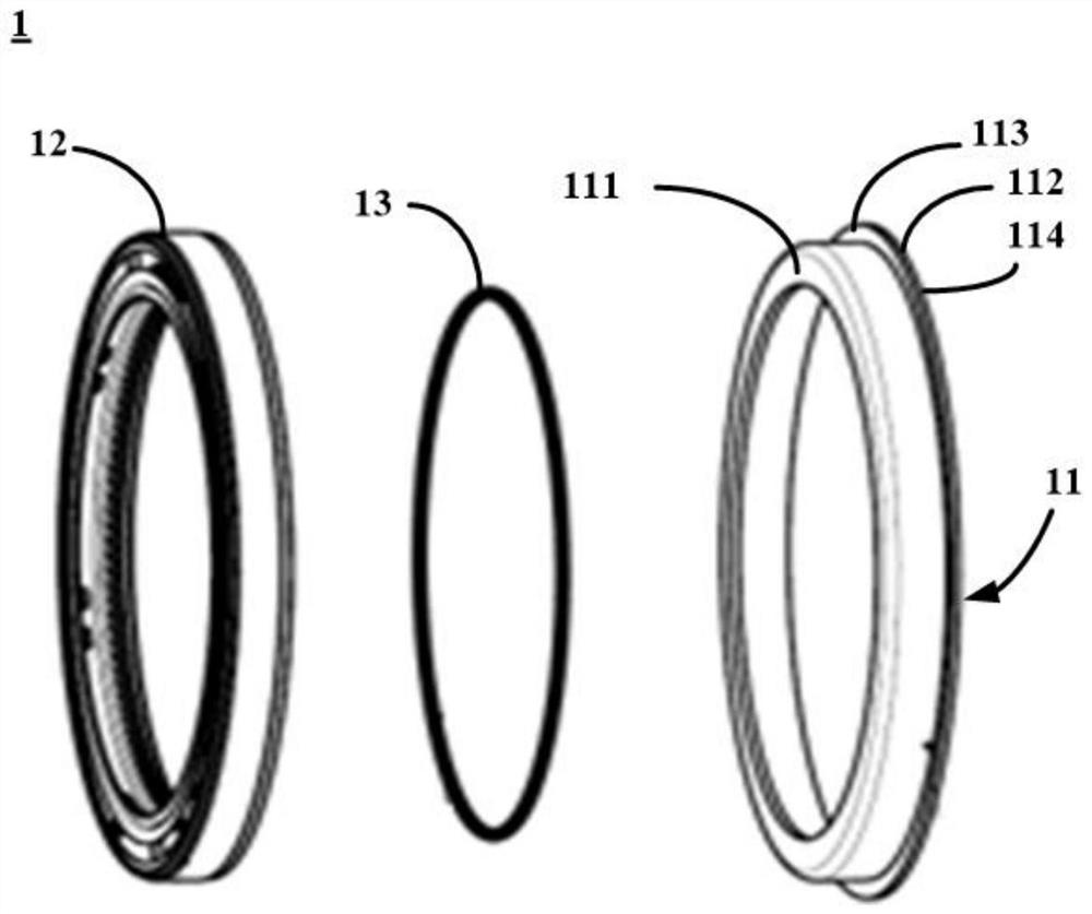
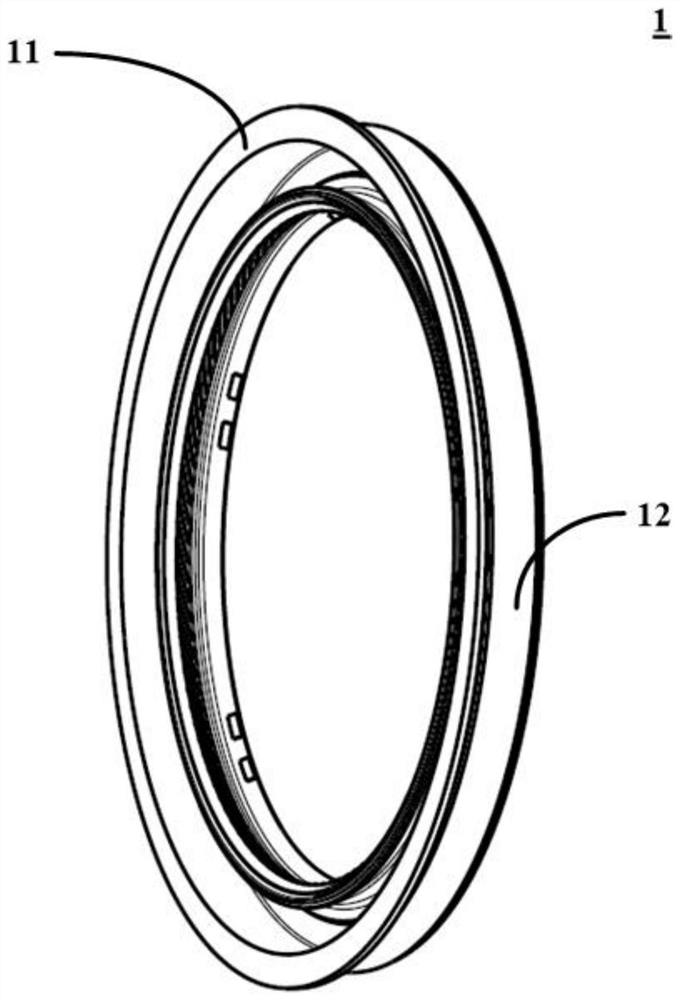
[0031] figure 1 A schematic perspective view of a crankshaft oil seal assembly according to an embodiment of the present invention is shown. The crankshaft oil seal assembly is assembled on the crankshaft of the crankcase. Such as figure 1 As shown, the crankshaft oil seal assembly includes an oil seal seat 2 and an oil seal 1 assembled on the oil seal seat 2 . figure 2 A schematic exploded view of an oil seal 1 according to an embodiment of the invention is shown. image 3 A schematic structural diagram of an oil seal 1 according to an embodiment of the present invention is shown. Such as figure 2 and image 3 As shown, the oil seal 1 includes a frame 11 and an annular sealing body 12 sleeved on the outside of the frame 11 . Wherein, the material of the skeleton 11 can be, for example, a metal material. The annular sealing body 12 is made of soft material, such as rubber. The skeleton 11 is composed of an annular skeleton body 111 and an annular boss 112 extending r...


PUM


Abstract

The invention provides a crankshaft oil seal assembly, a crankcase and a vehicle. The crankshaft oil seal assembly comprises an oil seal base and an oil seal assembled on the oil seal base; the oil seal comprises a framework and an annular sealing body arranged on the outer side of an annular framework body in a sleeved mode; the framework is composed of the annular framework body and an annular boss extending towards the radial outer side of the annular framework body along the annular framework body, and the annular boss is provided with a first side end face and a second side end face whichare opposite; and the first side end face and the assembling face of the oil seal base are assembled together, and the second side end face is closer to an engine than the first side end face, so that the oil seal is prevented from being disengaged from the oil seal base through limiting of the annular boss. According to the scheme of the invention, when the pressure of the crankcase is abnormally too large in the leakage test or operation process of the engine, acting force can be applied to the oil seal, so that the oil seal moves towards the side, making contact with air, of the oil seal base, and the oil seal is prevented from being disengaged from the oil seal base due to the limiting effect of the annular boss.

Description

technical field [0001] The invention relates to the technical field of vehicles, in particular to a crankshaft oil seal assembly, a crankcase and a vehicle. Background technique [0002] At present, the front end and rear end of the crankshaft are sealed with rubber oil seals during engine operation to prevent oil from seeping out during operation. The crankshaft oil seal used by the engine is currently generally used in the way that the rubber body is sleeved outside the metal frame, and the overall structure of the crankshaft oil seal is ring-shaped. The oil seal is pressed into the assembly cavity of the oil seal seat by a press-fitting machine, and is pressed from the side of the assembly cavity exposed to the air to the side close to the crankcase. During the press-fitting process, the press-fitting surface is the side end surface of the rubber body, and the oil seal is fixed in the fitting cavity through the interference between the rubber body and the assembly cavity...

Claims


Application Information

Patent Timeline
IPC IPC(8): F02F11/00F02F7/00F16J15/3252F16J15/3268
CPCF02F7/00F02F11/007F16J15/3252F16J15/3268
Inventor 张廷雷王瑞平安聪慧肖逸阁沈源尹建东
Owner ZHEJIANG GEELY HLDG GRP CO LTD
Learn More