Backing member for friction stir spot welding device, friction stir spot welding device, friction stir spot welding method, and joint structure

A technology of friction stir and point joining, which is applied in the direction of auxiliary equipment, welding equipment, manufacturing tools, etc., can solve the problems of reduced tool life, significant tool friction, and large-scale joint time of the device, so as to prevent the reduction of tool life and improve The effect of joint strength

Inactive Publication Date: 2021-02-09
KAWASAKI HEAVY IND LTD
View PDF7 Cites 0 Cited by
  • Summary
  • Abstract
  • Description
  • Claims
  • Application Information

AI Technical Summary

Problems solved by technology

However, if a tool with a complex shape is used, there is a problem that the wear of the tool becomes significant and the life of the tool decreases.
In addition, if a large-diameter tool is used, there is a problem of increasing the size of the device due to an increase in the tool pressurization force, or increasing the bonding time, thereby increasing the tact time.

Method used


Image

  • Backing member for friction stir spot welding device, friction stir spot welding device, friction stir spot welding method, and joint structure
  • Backing member for friction stir spot welding device, friction stir spot welding device, friction stir spot welding method, and joint structure
  • Backing member for friction stir spot welding device, friction stir spot welding device, friction stir spot welding method, and joint structure

Examples


Embodiment Construction

[0025] Embodiments will be described below with reference to the drawings.

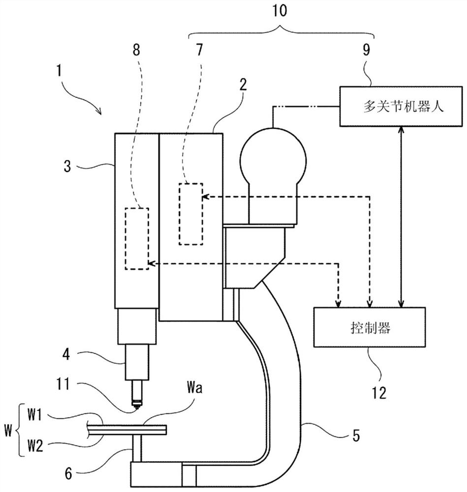
[0026] figure 1 It is a configuration diagram of the friction stir point welding device 1 according to the embodiment. Such as figure 1 As shown, the workpiece W is a pair of plate materials W1 and W2 overlapping each other, and is made of steel, for example. The friction stir spot welding apparatus 1 performs spot welding on an overlapping portion Wa of a pair of plate materials W1, W2. The friction stir spot welding apparatus 1 includes a base body 2 , a movable body 3 attached to the base body 2 , and a tool holder 4 protruding from the movable body 3 toward the workpiece W. As shown in FIG. The movable body 3 is attached to the base body 2 so as to be slidable and displaceable along the axis of the tool holding body 4 . The tool holder 4 is configured to be rotatable about its axis, and a tool 11 is detachably attached to a distal end portion of the tool holder 4 .

[0027] The tool 11 has: a...


PUM


Abstract

A backing member for a friction stir spot welding device is provided with a support surface that comes into contact with the back surface of an overlapping portion of a plurality of sheet members. Thesupport surface includes: a base surface which holds the overlapping portion between a shoulder portion of a tool and the base surface; and a projected surface which is projected further toward the overlapping portion side than the base surface, and holds the overlapping portion between a pin part of the tool and the projected surface.

Description

technical field [0001] The present invention relates to a gasket member of a friction stir point joining device, a friction stir point joining device, a friction stir point joining method, and a joint structure. Background technique [0002] In the assembly process of automobiles, airplanes, railway vehicles, etc., a plurality of plates are overlapped and joined by friction stir point joining (FSJ) to produce a joint structure. For example, in Patent Document 1, by supporting the overlapping portion of each plate material from the back side with a backing member, a tool having a protrusion (pressing pin) is pressed into the overlapping portion of each plate material from the front side while rotating, so that the overlapping portion The parts are softened by frictional heat and stirred, and then the tool is pulled out and cooled to join the plates. [0003] Patent Document 1: Japanese Patent Laid-Open No. 2001-321967 [0004] In a joint structure formed by friction stir po...

Claims


Application Information

Patent Timeline
IPC IPC(8): B23K20/12B23K37/06
CPCB23K20/12B23K37/06B23K2101/18
Inventor 村松良崇大桥良司三宅将弘福田拓也
Owner KAWASAKI HEAVY IND LTD
Why Eureka
Try Eureka