
Breathing mask with separable exhaust device

A technology of exhaust device and breathing mask, which is applied in the field of medical equipment, can solve the problems of long operation time, increased power consumption of supercharged turbofan, increased demand for air humidification, etc. Effects of medical care and user treatment

Active Publication Date: 2021-02-12
张奕晨
View PDF10 Cites 0 Cited by
  • Summary
  • Abstract
  • Description
  • Claims
  • Application Information

AI Technical Summary

Problems solved by technology

In the process of use, the existing masks, especially the mouth-nose breathing masks used in the clinical treatment of lung diseases, lack the management of the airflow in the mask in design, and the following problems generally exist: the position of the air intake pipe and the exhaust hole are close, compared with the user's exhaled airflow There is a shorter path to the vent hole, so it is easier to escape from the vent hole, and the user's exhaled airflow is relatively difficult to discharge, and it is easy to accumulate in the mask; in order to dilute and discharge the user's exhaled gas, more vent holes need to be designed Leakage
When the air leakage of the designed exhaust hole increases, in order to provide accurate pressure, the power consumption of the supercharged turbofan will increase accordingly, and it will be difficult to improve the response speed of pressure conversion, and the demand for air humidification will also increase; in addition, Some daily needs of the user, such as expectoration and drinking water, can only be completed by removing the mask first. The operation is more complicated and the operation time is longer. For critically ill patients, sometimes it cannot respond to the user's ventilator ventilation treatment needs in time.

Method used


Image

  • Breathing mask with separable exhaust device
  • Breathing mask with separable exhaust device
  • Breathing mask with separable exhaust device

Examples


Embodiment Construction

[0016] Embodiments of the present invention are described below with reference to the drawings, in which like parts are denoted by like reference numerals.

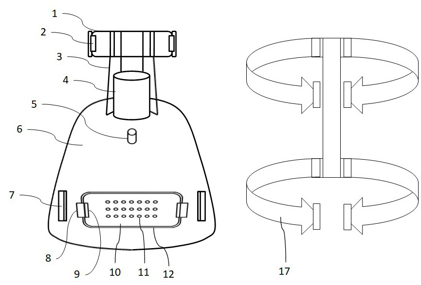
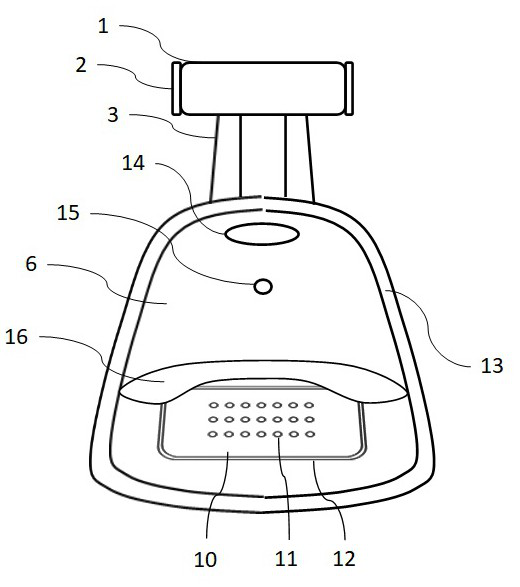
[0017] figure 1 To show the side of the mask facing the environment, figure 2 Shows the side of the mask facing the user.

[0018] The mask fixed headband 17 is made of elastic material and has four ends, each of which is provided with a hook; the forehead support 1 is provided with a forehead fixing buckle 2, one on each side; the forehead support 1 and the mask body 6 pass through the connecting rod 3 Connection; the mask intake pipe 4 is fixedly arranged on the upper part of the mask body 6 and communicates with the air intake through hole 14 on the mask body, and the oxygen interface 5 is fixedly arranged on the mask body 6 and communicates with the oxygen through hole 15; the mask body 6 is fixedly arranged There are body fixing buckles 7, one each on the left and right sides; the mask body 6 has a relatively larg...


PUM


Abstract

The invention structurally considers management of airflow in a mask, and provides a breathing mask with a separable exhaust device. The air inlet pipe arranged on the breathing mask is far away fromthe exhaust device, and the exhaust device is arranged at the position closest to the mouth and nose of a user, so that air exhaled by the user is easily exhausted out of the mask. The air inlet pipeis far away from the exhaust device, so that air supply flow in the mask can flow in one direction, interference with user exhaled air flow exhaust is avoided, and accumulation of the exhaled air flowin the mask is reduced. The separable exhaust device can be conveniently and quickly operated, cleaned and nursed by medical staff, and meanwhile, sputum excretion of a user is also facilitated; dueto the application of the flow limiting structure of the exhaust device, the air leakage of the system can be reduced, the burden of the turbocharging fan can be reduced, the performance index requirement can be reduced, and the pressure conversion reaction speed is increased.

Description

technical field [0001] The invention relates to the field of medical equipment, in particular to a breathing mask with a detachable exhaust device. Background technique [0002] Positive pressure non-invasive ventilation is a technology in which the user connects to the ventilator through a breathing mask, and the ventilator provides positive pressure airflow to assist or replace the patient's breathing. Its application has gradually increased in recent years. Respiratory masks are a key component of non-invasive ventilation. There are many types of masks on the market, including nasal masks, mouth and nose masks, and nasal pillows. The air intake pipe of the breathing mask is generally placed at the mouth and nose, and the exhaust hole is arranged near the air intake pipe, or a plurality of small exhaust holes are directly opened on the mask. In the process of use, the existing masks, especially the mouth-nose breathing masks used in the clinical treatment of lung diseases...

Claims


Application Information

Patent Timeline
Patent Type & Authority Applications(China)
IPC IPC(8): A61M16/06A61M16/08A61M16/00
CPCA61M16/06A61M16/0633A61M16/0816A61M16/0003
Inventor 不公告发明人
Owner 张奕晨
Learn More