
Aluminum plate surface polishing device

A surface polishing, aluminum plate technology, applied in surface polishing machine tools, grinding drives, grinding/polishing equipment, etc., can solve the problem that the polishing roller can only handle individual parts of the surface of the aluminum plate, and can only be polished when the part is bulging. To the middle of the aluminum plate, the aluminum plate cannot be polished, etc., to improve the polishing quality, reduce labor intensity, and achieve the effect of automation

Inactive Publication Date: 2021-02-12
河南龙盛新材料科技有限公司
View PDF6 Cites 5 Cited by
  • Summary
  • Abstract
  • Description
  • Claims
  • Application Information

AI Technical Summary

Problems solved by technology

However, when the existing polishing machine is polishing, if the aluminum plate itself is not flat enough, it is easy to cause the polishing roller to only process individual parts on the surface of the aluminum plate, and many positions on the surface of the aluminum plate still cannot be polished.
For example, when the aluminum plate is tilted on both sides, the polishing roller can only grind to the edge of the aluminum plate, and the middle of the aluminum plate cannot be polished;

Method used


Image

  • Aluminum plate surface polishing device
  • Aluminum plate surface polishing device
  • Aluminum plate surface polishing device

Examples


Embodiment Construction

[0037]In order to make the objectives, technical solutions and advantages of the present invention clearer, the technical solutions of the present invention will be described in detail below. Obviously, the described embodiments are only a part of the embodiments of the present invention, rather than all the embodiments. Based on the embodiments of the present invention, all other implementations obtained by a person of ordinary skill in the art without creative work shall fall within the protection scope of the present invention.

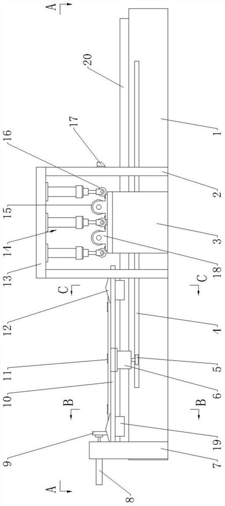
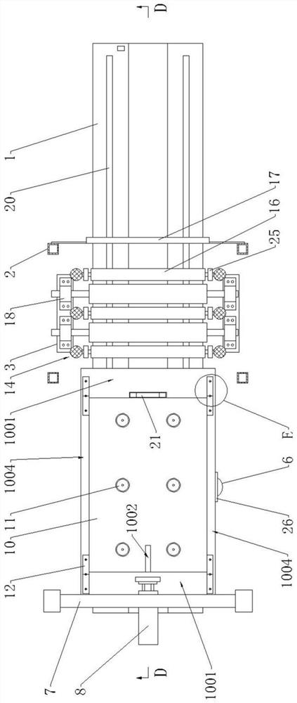
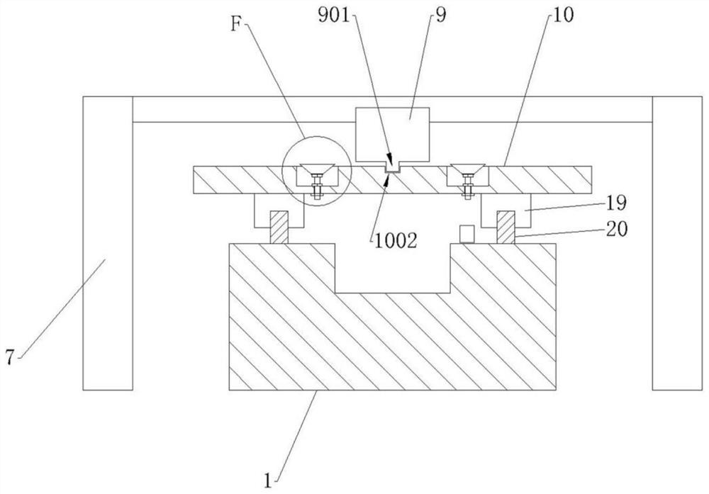
[0038]SeeFigure 1-Figure 17As shown, the present invention provides an aluminum plate surface polishing device, which includes a base 1, a processing platform 10, a frame, an elastic column 14, a flattening roller 16, and a polishing rod 15. The upper end of the base 1 is provided with two parallel to each other Each of the linear guide rails 20 is provided with two sliders 19; the side of the base 1 is provided with a rack 4 parallel to the linear guide ra...


PUM


Abstract

The invention discloses an aluminum plate surface polishing device which comprises a base, a machining platform, a rack, elastic columns, flattening rollers and polishing rollers. A linear guide railand a rack are arranged on the base. A sliding block is arranged on the linear guide rail. The machining platform is fixed above the sliding block, and a first motor is arranged below the machining platform; a stepped hole is formed in the machining platform, and a vacuum chuck is arranged in the stepped hole; a longitudinal milling groove and a transverse milling groove are formed in the machining platform, and an inclined wedge is arranged in the longitudinal milling groove; the rack is composed of a supporting beam and a top plate, and the top plate stretches across the base; at least two flattening rollers are provided, and the two ends of each flattening roller are connected with the lower ends of the elastic columns, and the upper ends of the elastic columns are fixed to the top plate; and rigid rolling wheels are arranged at the two ends of each flattening roller. The polishing roller is arranged between every two adjacent flattening rollers, liftable racks are arranged on the two sides of the base, and the two ends of each polishing roller are connected with the racks. According to the aluminum plate surface polishing device, automatic polishing operation of an aluminum plate is achieved, and the aluminum plate surface polishing device benefits improvement of the polishing efficiency and the polishing quality.

Description

Technical field[0001]The invention relates to the technical field of aluminum plate processing equipment, in particular to an aluminum plate surface polishing device.Background technique[0002]Aluminum plate refers to aluminum material with a thickness between 0.2mm and 500mm, a width of 200mm or more, and a length of 16m or less, called aluminum plate or aluminum sheet, the thickness of less than 0.2mm is called aluminum, and the width of 200mm is called as row Wood or bar. Aluminum plate refers to the rectangular plate made by rolling aluminum ingot, which is divided into pure aluminum plate, alloy aluminum plate, thin aluminum plate, medium thickness aluminum plate and pattern aluminum plate. Aluminum plates are mainly used in lighting, mechanical parts processing, architectural appearance, interior decoration, aerospace and military fields.[0003]After the aluminum plate is polished, not only the surface flatness is better, the product grade is higher, but the surface gloss is als...

Claims


Application Information

Patent Timeline
IPC IPC(8): B24B27/00B24B29/02B24B41/06B24B47/00B24B47/20B21D1/02
CPCB24B29/02B24B27/0076B24B27/0069B24B41/06B24B47/20B24B47/00B21D1/02
Inventor 蔡玉田苏志超
Owner 河南龙盛新材料科技有限公司
Learn More