

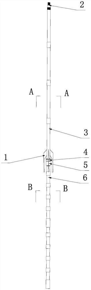
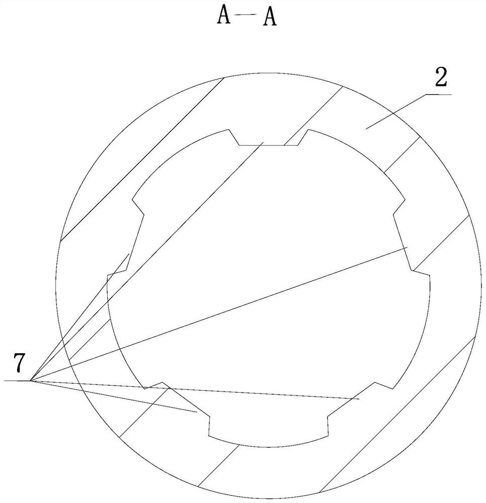
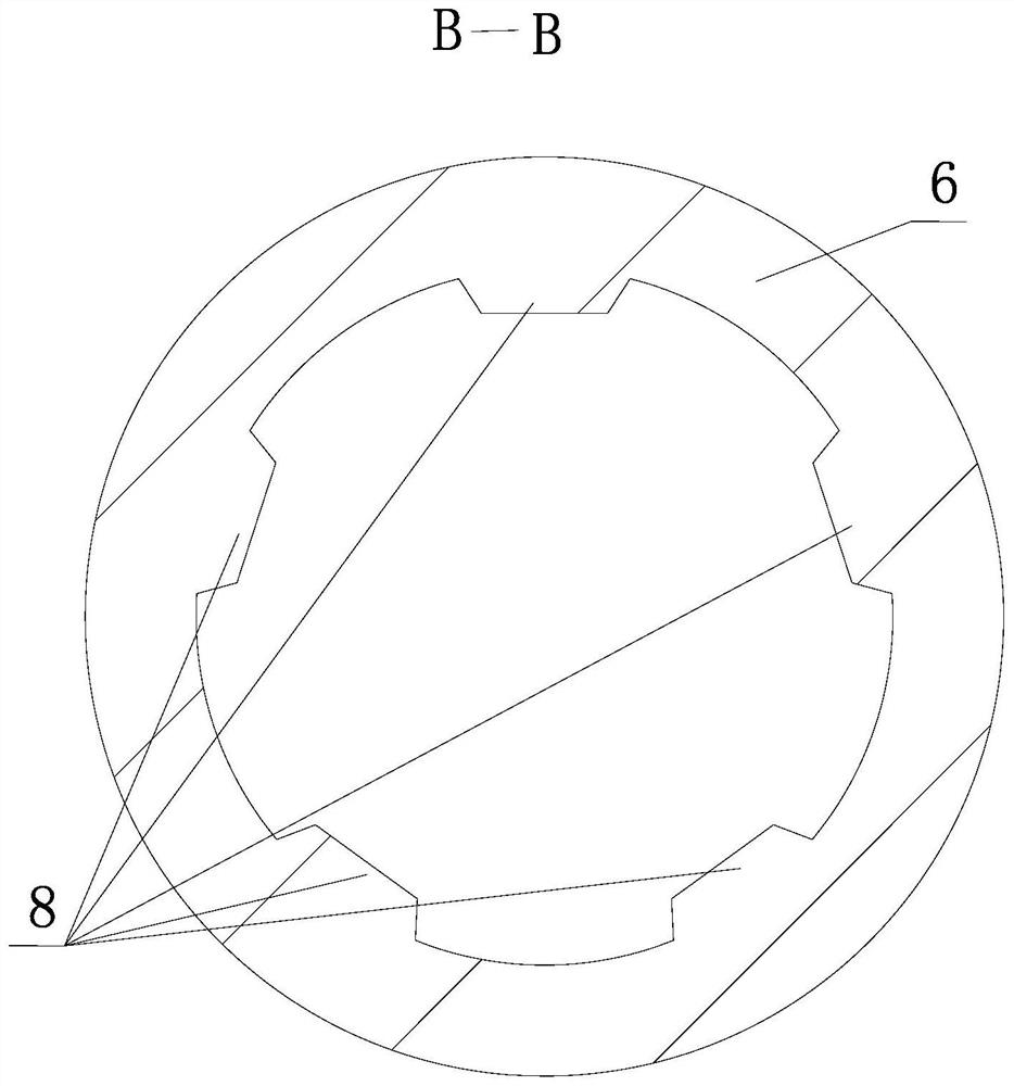
Composite foundation piles composed of steel pipe piles and cement-soil piles
A technology of cement-soil piles and steel pipe piles, applied in sheet pile walls, infrastructure engineering, construction, etc., can solve the problems of limited uplift or compressive bearing capacity of piles, instability, and too late to exert themselves.
- Summary
- Abstract
- Description
- Claims
- Application Information
AI Technical Summary
Problems solved by technology
Method used
Image

Examples
Embodiment Construction
[0030] The specific embodiments of the present invention will be further described below in conjunction with the accompanying drawings. What needs to be declared here is that the descriptions of these embodiments are used to help understand the present invention, but are not intended to limit the present invention. In addition, the technical features involved in the various embodiments of the present invention described below may be combined with each other as long as they do not conflict with each other.
[0031] Such as figure 1 , figure 2 , image 3 , Figure 4 , Figure 5 , Figure 6 , Figure 7 , Figure 8 , Figure 9 , Figure 10 , Figure 11 , Figure 12 , Figure 13 shown.
[0032] see Figure 13 , the soft soil area, the soil, that is, the soil structure, generally from the surface to the lower layer, that is, from shallow to deep, is a soft soil layer 42 such as a muddy clay layer, a neutral soil layer 36 such as a silty clay layer, and a hard soil lay...
PUM
 Abstract
Description
Claims
Application Information