Rotor assembly, compressor and air conditioner

A component and rotor technology, applied in the field of gas compression devices, can solve the problems of increased windward area of ​​the main balance weight, enhanced exhaust slapping effect, and increased oil discharge rate of the compressor, etc.

Pending Publication Date: 2021-02-12
GREE ELECTRIC APPLIANCES INC
View PDF0 Cites 4 Cited by
  • Summary
  • Abstract
  • Description
  • Claims
  • Application Information

AI Technical Summary

Problems solved by technology

An excessively high main balance weight will increase the windward area of ​​the main balance weight and strengthen the slapping effect on the exhaust gas, causing the oil droplets flowing with the exhau

Method used


Image

  • Rotor assembly, compressor and air conditioner
  • Rotor assembly, compressor and air conditioner
  • Rotor assembly, compressor and air conditioner

Examples


Embodiment 1

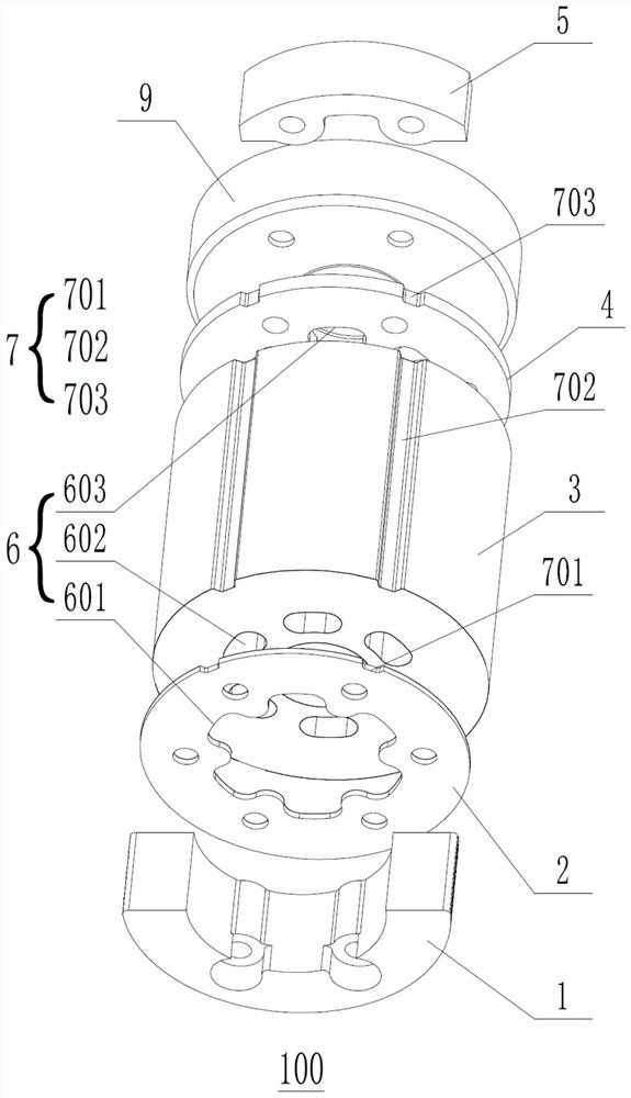
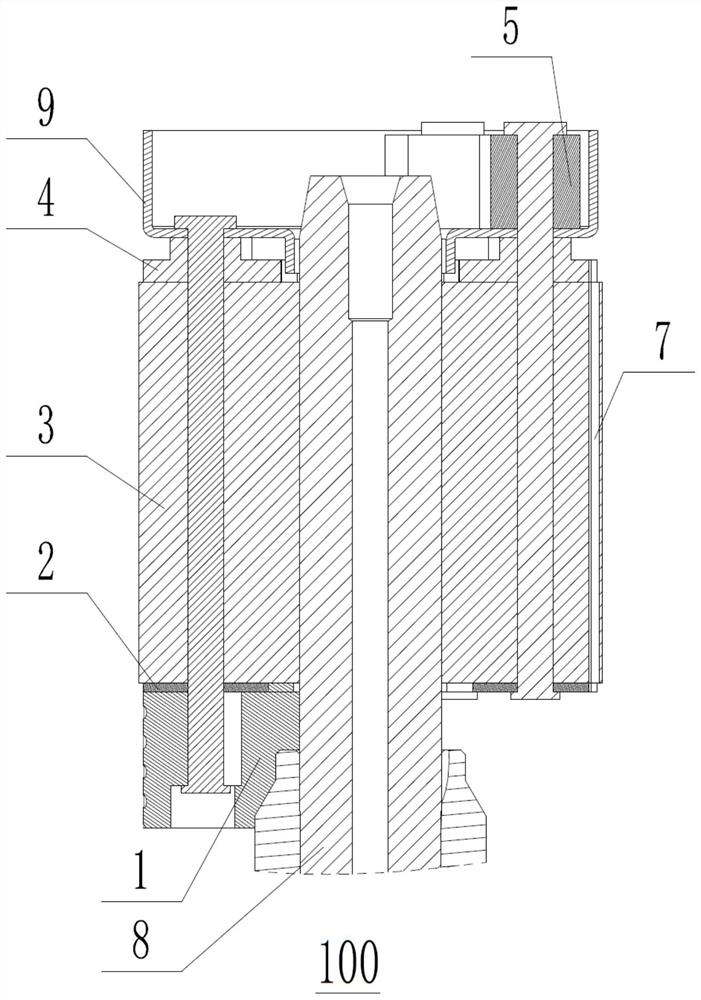
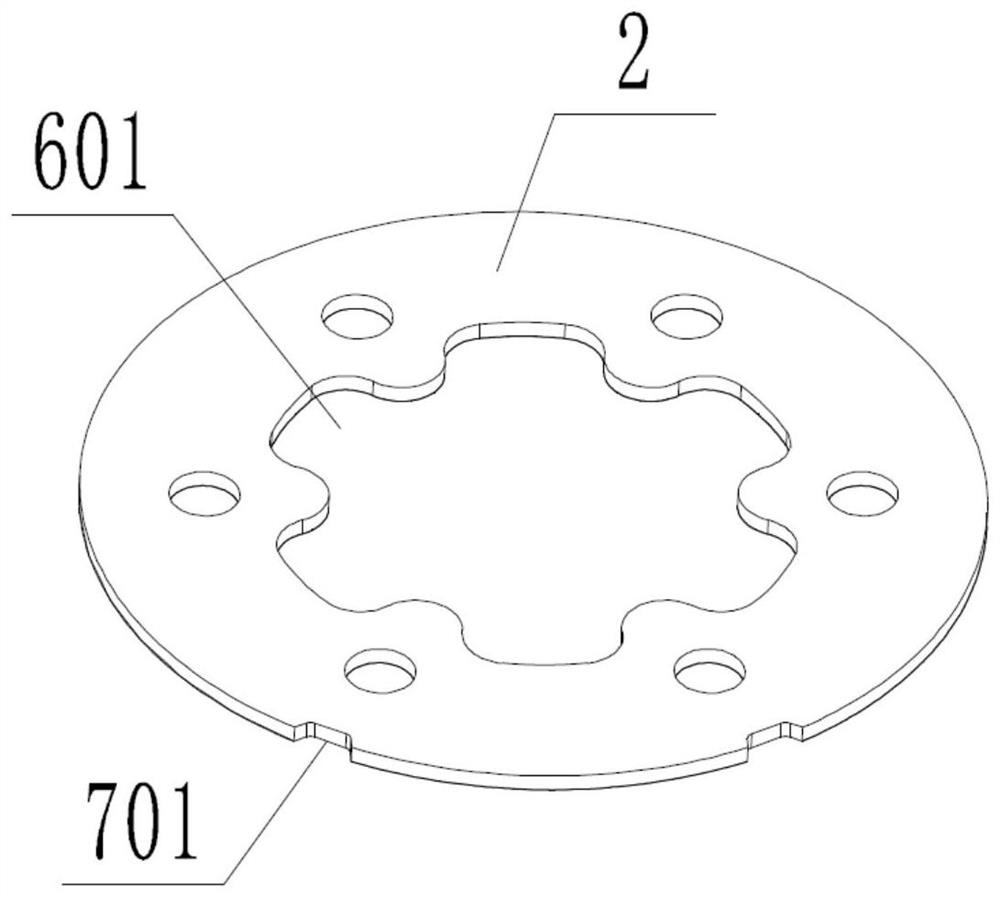
[0047] Such as figure 1 with 2As shown, the embodiment of the present invention provides a rotor assembly 100, which is applied to a single-cylinder rolling rotor compressor. The rotor assembly 100 includes a main balance weight 1, a first magnetic shield 2, a rotor Iron core 3, second magnetic shielding plate 4, oil shielding cap 9 and auxiliary balance weight 5, the inside of the first magnetic shielding plate 2, rotor core 3 and second magnetic shielding plate 4 are uniformly arranged with several main poles around the central axis. The circulation passage 6, the first magnetic shielding plate 2, the rotor core 3 and the second magnetic shielding plate 4 are formed with a secondary circulation passage 7 penetrating in the axial direction, and the main balance weight 1 is located on the rotor core 3 On one side of the central axis, the secondary flow channel 7 and the secondary balance weight 5 are located on the other side of the central axis of the rotor core 3 . During ...

Embodiment 2

[0080] Such as figure 1 , 2 As shown in and 10-12, the embodiment of the present invention provides a rotor assembly 100, which is applied to a single-cylinder rolling rotor compressor. The rotor assembly 100 includes a main balance weight 1, a first magnetic stop Plate 2, rotor core 3, second magnetic shielding plate 4, oil shielding cap 9 and auxiliary balance weight 5, the inside of the first magnetic shielding plate 2, rotor core 3 and second magnetic shielding plate 4 is uniform around the central axis Several main flow channels 6 are provided, the main balance weight 1 is located on one side of the central axis of the rotor core 3 , and the auxiliary balance weight 5 is located on the other side of the central axis of the rotor core 3 . During the specific use of the rotor assembly, the central axis of the rotor assembly 100 is set vertically, the main balance weight 1 is located at the lower end of the rotor assembly, the auxiliary balance weight 5 is located at the up...


PUM


Abstract

The invention relates to the technical field of gas compression devices, in particular to a rotor assembly, a compressor and an air conditioner. A plurality of main circulation channels are evenly formed in a first magnetic baffle, a rotor iron core and a second magnetic baffle of the rotor assembly around the central axis, auxiliary circulation channels which are through in the axial direction are formed in the first magnetic baffle, the rotor iron core and the second magnetic baffle, a main balance block is located on one side of the central axis, and auxiliary circulation channels are located on the other side of the central axis. The auxiliary circulation channels improve a balance system, the height of the main balance block in the axial direction can be reduced, then the windward area of the main balance block is reduced, the clapping effect on exhaust gas flow is weakened, tiny liquid drops are reduced, and then the amount of oil entering an upper cavity of a motor along with flowing of a refrigerant is reduced. The auxiliary circulation channels increase the flow flowing through the circulation channels, improves the internal circulation of the compressor, increases the stator trimming return flow, and realizes secondary oil separation. The effects of two oil separation are integrated, and the oil spitting rate of the compressor is effectively reduced.

Description

technical field [0001] The present application relates to the technical field of gas compression devices, in particular, to a rotor assembly, and to a compressor and an air conditioner including the rotor assembly. Background technique [0002] At present, the refrigeration compressors used in household air conditioners are mainly rolling rotor compressors, and the air conditioning systems below 3 HP mainly use single-cylinder rolling rotor compressors. Since the center of the crankshaft is not concentric with the axis of the motor rotor, it is necessary to balance the inertial force and moment caused by the eccentric mass of the eccentric part of the crankshaft during the rotation process. [0003] The existing balance system of the single-cylinder rolling rotor compressor consists of the main balance weight located at the lower part of the motor rotor and the auxiliary balance weight located at the upper part of the motor rotor. In order to better balance the inertial forc...

Claims


Application Information

Patent Timeline
IPC IPC(8): F04C29/00F04C29/02F04C23/02H02K7/04
CPCF04C23/02F04C29/0021F04C29/026H02K7/04
Inventor 刘喜兴于潇逍刘国良吕丹丹刘靖徐博文
Owner GREE ELECTRIC APPLIANCES INC
Why Eureka
Try Eureka