
Bladeless fan

A bladeless fan, round shell technology, used in machines/engines, non-displacement pumps, mechanical equipment, etc., can solve the problems of rising cost, large heat generation, and high requirements for heat dissipation of the device, and achieve structural optimization and high air output speed. , the effect of gathering the wind effect

Inactive Publication Date: 2021-02-12
YANSHAN UNIV
View PDF7 Cites 0 Cited by
  • Summary
  • Abstract
  • Description
  • Claims
  • Application Information

AI Technical Summary

Problems solved by technology

[0003] The purpose of the present invention is to solve the problems of rising cost, large calorific value, and high requirements for heat dissipation of the device

Method used


Image

  • Bladeless fan
  • Bladeless fan
  • Bladeless fan

Examples


Embodiment Construction

[0030] The technical solutions of the present invention will be clearly and completely described below through specific embodiments. Apparently, the described embodiments are only some of the embodiments of the present invention, but not all of them. Based on the embodiments of the present invention, all other embodiments obtained by persons of ordinary skill in the art without creative efforts fall within the protection scope of the present invention.

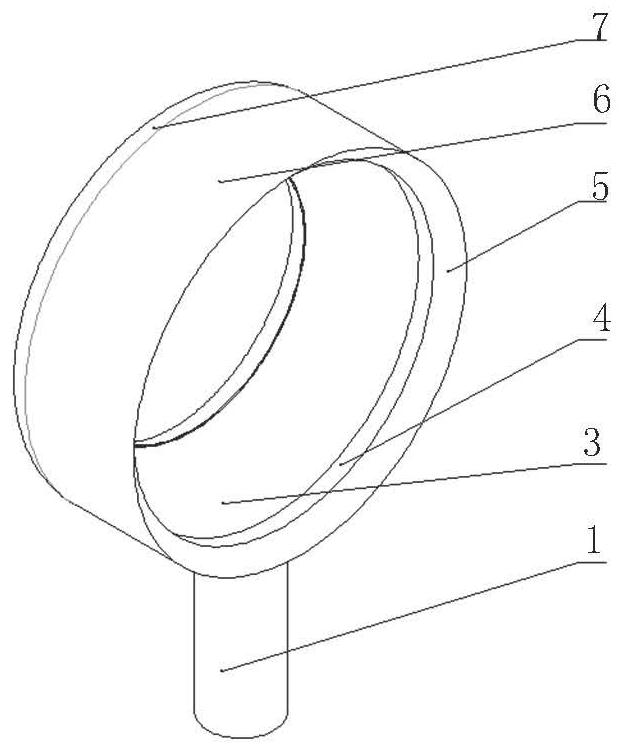
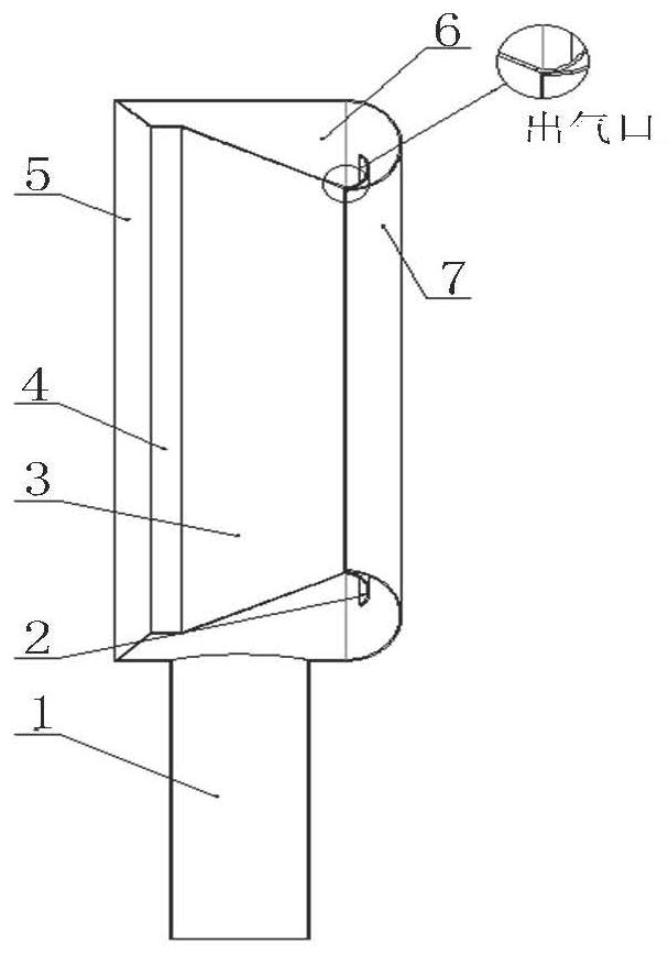
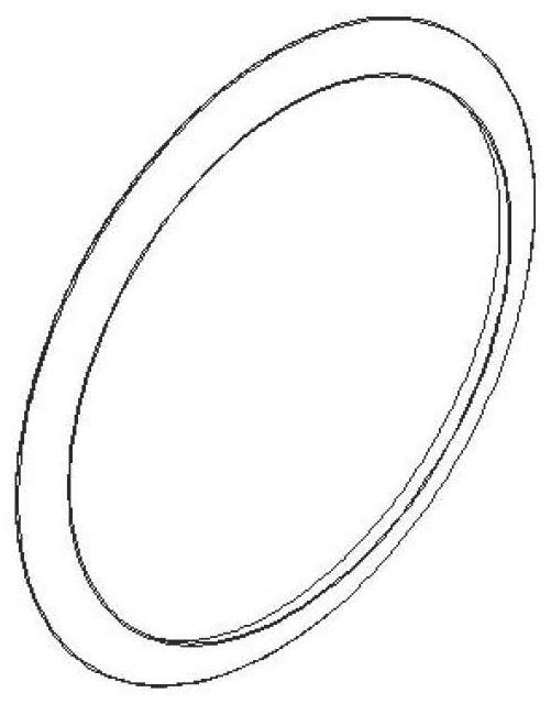
[0031] Such as Figure 1-9 As shown, the bladeless fan includes an air inlet (1), an inner shell (2), an outer shell 1 (3), a circular shell 1 (4), an outer shell 2 (5), and a circular shell 2 (6) , circular shell 3 (7); Inlet duct (1) one port fixes circular shell 2 (6), and circular shell 2 (6) one end annular surface fixes the outer annular surface of circular shell 3 (7), and circular shell 3 (7) ) the inner wall is provided with an inner shell (2), the other end of the circular shell 2 (6) is fixed on the outer annular ...


PUM


Abstract

The invention relates to the technical field of bladeless fans, and particularly relates to a bladeless fan. The bladeless fan comprises an air inlet channel, an inner shell, an outer shell 1, a circular shell 1, an outer shell 2, a circular shell 2 and a circular shell 3, wherein the circular shell 2 is fixed to one end opening of the air inlet channel; the outer ring face of the circular shell 3is fixed to the ring face of one end of the circular shell 2; the inner shell is arranged on the inner wall of the circular shell 3; the outer ring face of the outer shell 2 is fixed to the ring faceof the other end of the circular shell 2; one ring face of the circular shell 1 is fixed to the inner ring face of the outer shell 2; and the outer shell 1 is fixed to the other ring face of the circular shell 1. According to the bladeless fan, through the arc design, the bladeless fan can be stressed evenly under the extreme working condition, and the situation of stress concentration is prevented; the inner shell is mounted inside to achieve gradual pressure change, and the vibration amplitude and vibration frequency of the bladeless fan are reduced; and the circular shell 1 is mounted, theair outlet effect is more concentrated, air is blown out in the horizontal direction, and the air blowing distance is longer.

Description

technical field [0001] The invention relates to the technical field of bladeless fans, in particular to a bladeless fan. Background technique [0002] At present, the bladeless fans sold in the market mainly work through their own small-power fixed motors, but with the development of industry, the demand for bladeless fans is no longer simply satisfied. In the neighborhood of civilian use, high-power, The demand for large-flow bladeless fans is increasing. If you still use the original low-power household bladeless fans and increase the power of the bottom motor to increase the wind effect of the bladeless fan, you need to configure a higher-power motor. This leads to problems such as rising production costs, increased heat production, and higher heat dissipation requirements for devices. Contents of the invention [0003] The purpose of the present invention is to solve the problems of rising cost, large calorific value, and high requirements for heat dissipation of the ...

Claims


Application Information

Patent Timeline
Patent Type & Authority Applications(China)
IPC IPC(8): F04F5/16F04F5/44F04F5/46
CPCF04F5/16F04F5/44F04F5/46
Inventor 张晋黄橙橙陈星隋佳鑫
Owner YANSHAN UNIV
Learn More