Soap film water hole test device
A test device, membrane water technology, applied in the direction of measuring device, fluid dynamics test, machine/structural component test, etc., can solve the problems of lack of effective control of flow velocity and unchangeable test parameters, etc., to achieve liquid stability and eliminate pulsation , the effect of increasing the movement speed
- Summary
- Abstract
- Description
- Claims
- Application Information
AI Technical Summary
Problems solved by technology
Method used
Image
Examples
Embodiment 1
[0050]This embodiment provides a soap film water hole test device, which can make the flow rate of the soap film water hole test device meet the test requirements of high flow rate, and can effectively control the flow rate.
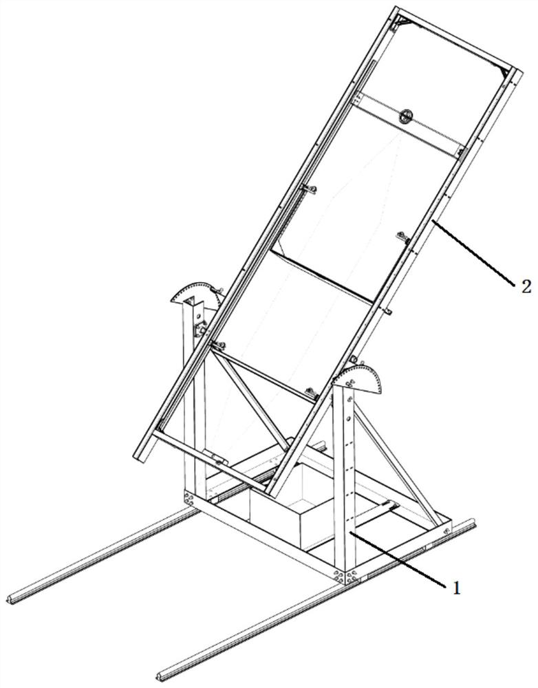
[0051] Such as figure 2 As shown, the soap film water hole test device comprises: an outer frame 1, an inner frame 2 and a position locking mechanism;
[0052] Wherein the internal frame 2 is the test main device fixed in the external frame 1, and the two opposite ends of the internal frame 2 (such as figure 2 The shown left and right ends) are supported on the external frame 1 by bearings, and can rotate around the bearing axis (horizontal direction). After rotating to a set angle, the position is locked by the position locking mechanism.
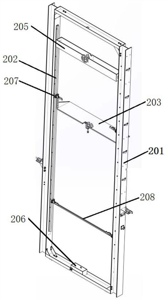
[0053] Such as image 3 and Figure 4 As shown, the internal frame 2 includes: a bracket 201, an optical axis seat, a hook, a silk thread 204, an upper water tank 205, a lower water tank 206, a bracket slider 20...
Embodiment 2
[0067] On the basis of the above-mentioned embodiment 1, in order to further increase the flow velocity of the soap film, a thread traction mechanism is added; the thread traction mechanism drives the two silk threads 204 used to form the guide frame to move downward synchronously, thereby assisting in controlling the flow velocity.
[0068] Such as Figure 7 As shown, the thread traction mechanism includes: traction rollers, guide hooks 301, thread convergence buckets 302, traction motors, dampers and winding reels; wherein the traction rollers and silk thread convergence buckets are fixed on the internal frame 2; the connection relationship is: through Two parallel linear slide rails 303 are connected to the optical axis seats at the corresponding positions on the left and right side panels of the internal frame 2, and each linear slide rail 303 is provided with two guide hooks 301 slidingly matched with it, and two silk threads 204 or so After being arranged side by side, t...
Embodiment 3
[0073] On the basis of the above-mentioned embodiment 1 or embodiment 2 or embodiment 3, specifically, the position locking mechanism adopts a spring lock, and a spring lock is provided on the outside of the left and right side plates of the inner frame 2 bracket 201, and the spring lock passes through the corner code (The corner code is a triangular bracket) fixed on the side plate; the position of the spring lock corresponds to the position of the index plate on the outer frame of the corresponding side, and the index plate is provided with a locking hole for matching with the mandrel of the spring lock; it needs to be rotated When the inner frame 2 is in place, pull out the mandrel of the spring lock, and when the inner frame 2 is rotated to the set angle position, insert the mandrel of the spring lock into the locking hole on the index plate, thereby fixing the inner frame 2.
PUM
 Abstract
Description
Claims
Application Information
 - R&D
- Intellectual Property
- Life Sciences
- Materials
- Tech Scout
- Unparalleled Data Quality
- Higher Quality Content
- 60% Fewer Hallucinations
Browse by: Latest US Patents, China's latest patents, Technical Efficacy Thesaurus, Application Domain, Technology Topic, Popular Technical Reports.
© 2025 PatSnap. All rights reserved.Legal|Privacy policy|Modern Slavery Act Transparency Statement|Sitemap|About US| Contact US: help@patsnap.com


