
Soil moisture content real-time monitoring, regulating and controlling system based on Internet of Things

A soil moisture, real-time monitoring technology, applied in soil material testing, measuring devices, instruments, etc., can solve the problems of pile instability, damage, waste of resources, etc., and achieve the effect of increasing the smoothness of movement

Inactive Publication Date: 2021-02-12
顾晓东
View PDF0 Cites 3 Cited by
  • Summary
  • Abstract
  • Description
  • Claims
  • Application Information

AI Technical Summary

Problems solved by technology

[0003] For the detection of soil moisture in paddy fields, the detection system is generally set up by manually inserting detection piles. This setting can only detect soil moisture at fixed points, and cannot detect different paddy fields in real time. Existing methods for paddy fields The problems existing in soil moisture detection are as follows:
[0004] 1. It is necessary to set multiple monitoring points to detect the soil moisture when setting the detection head by inserting piles. This setting causes waste of resources, and it is difficult to manually install piles in the paddy field, and the inserted The pile is unstable and prone to dumping in the paddy field;
[0005] 2. The soil detection sensor is generally exposed on the outside, and manual handling or transfer is likely to cause damage to it. After the soil moisture detection sensor detects the soil quality, it is necessary to manually remove the soil on the detection plate

Method used


Image

  • Soil moisture content real-time monitoring, regulating and controlling system based on Internet of Things
  • Soil moisture content real-time monitoring, regulating and controlling system based on Internet of Things
  • Soil moisture content real-time monitoring, regulating and controlling system based on Internet of Things

Examples


Embodiment Construction

[0032] In order to make the technical means, creative features, objectives and effects achieved by the present invention easy to understand, the present invention will be further elaborated below in combination with specific diagrams. It should be noted that, in the case of no conflict, the embodiments in the present application and the features in the embodiments can be combined with each other.

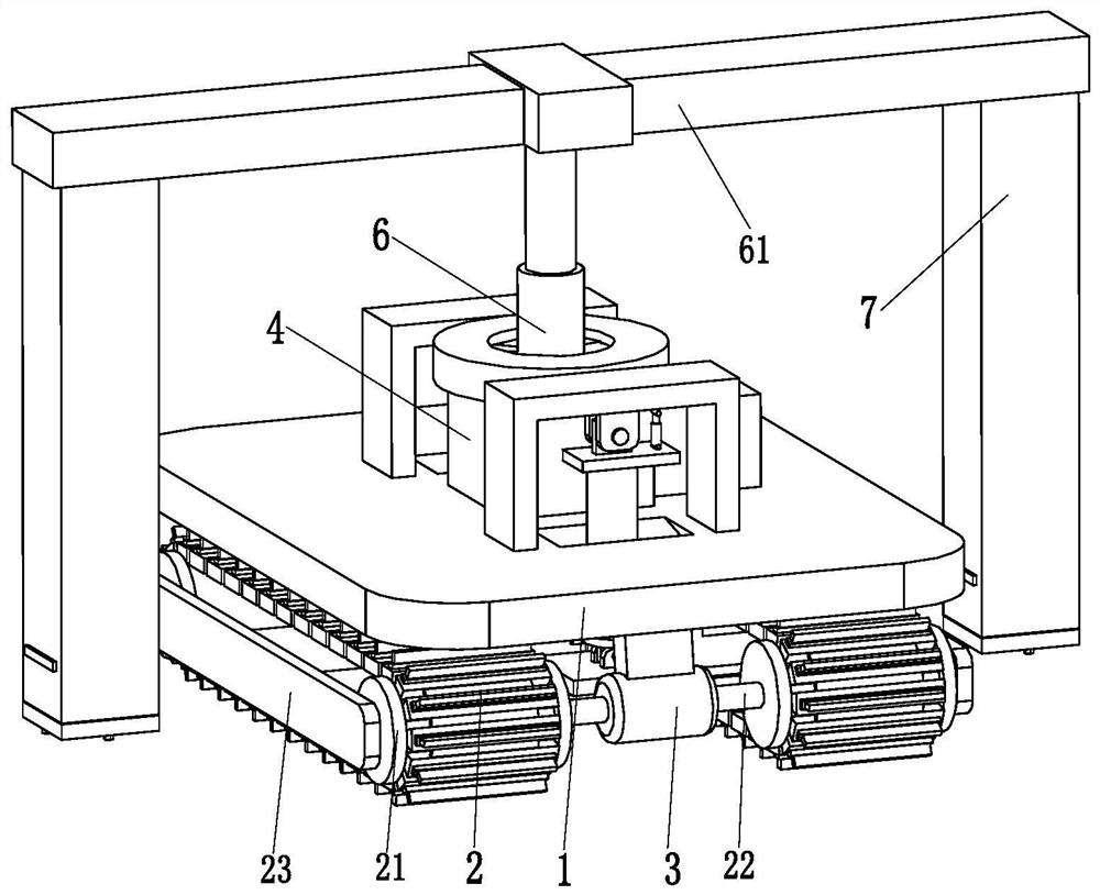
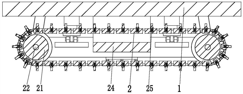
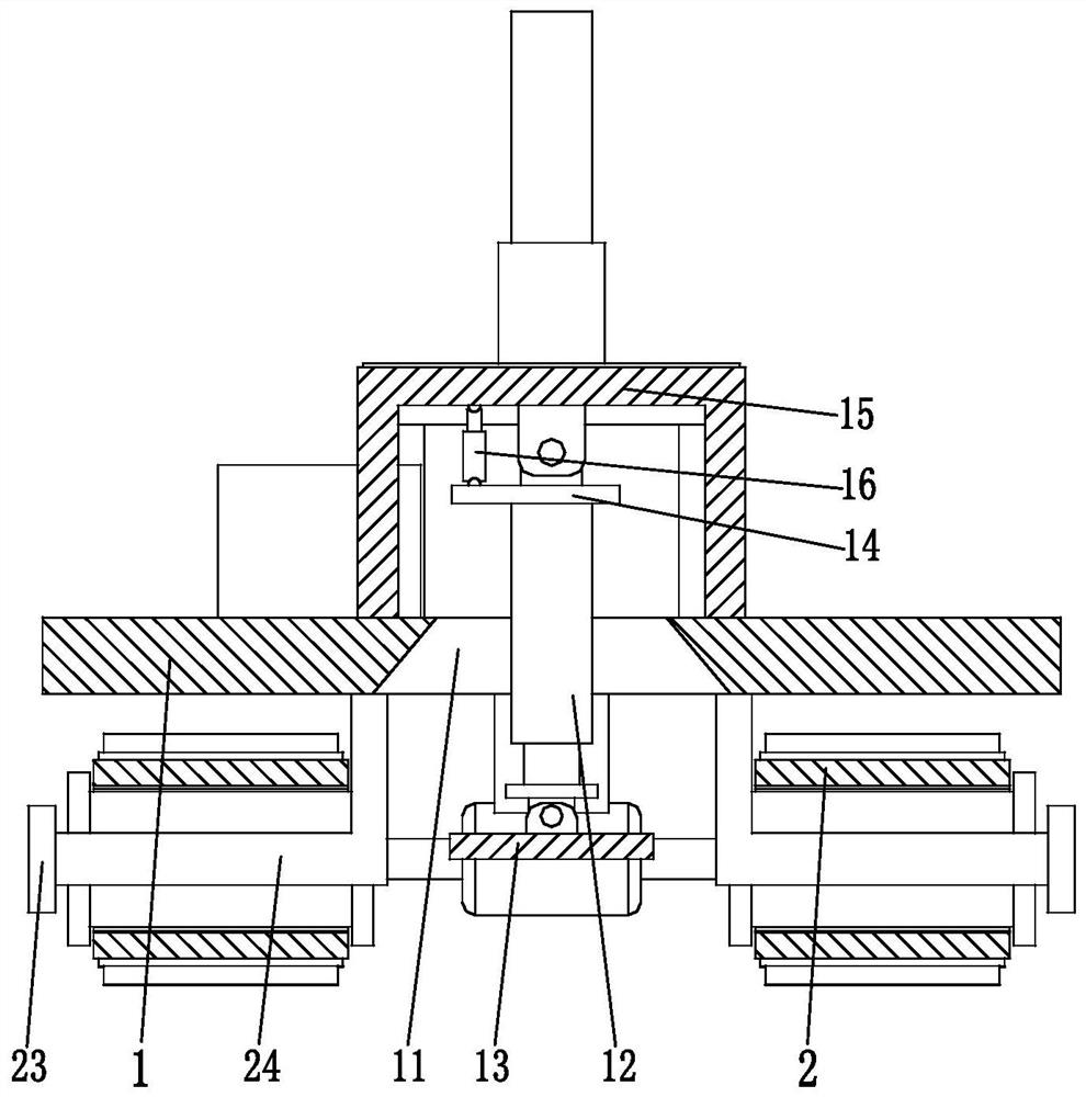
[0033] like Figure 1 to Figure 8As shown, a real-time monitoring and control system for soil moisture based on the Internet of Things includes a support plate 1, a crawler belt 2, a mobile motor 3, a support frame 4, a rotating motor 5, a telescopic column 6 and a detection mechanism 7, and the support plate 1 Track wheels 21 are arranged at both ends of the track wheels 2 respectively. The track wheels 21 are I-shaped structures. The track wheels 21 are installed on the transmission shaft 22. Two track wheels on the track 2 The outer end transmission support plate 23 of 21, the o...


PUM


Abstract

The invention relates to a soil moisture content real-time monitoring, regulating and controlling system based on an Internet of Things. The system comprises a supporting plate, a crawler belt, a moving motor, a supporting frame, a rotating motor, a telescopic column and a detection mechanism; the rotating motor is installed on the upper side face of the supporting plate through a motor sleeve, atelescopic column is installed on an output shaft of the rotating motor, a detection supporting column is arranged on the upper side face of the telescopic column, the bottoms of the two ends of the detection supporting column are each provided with a detection mechanism, and a center control mechanism is arranged on the outer side of the supporting frame. The system can solve the problems that when soil moisture content detection is carried out on an existing rice field, pile inserting setting is difficult to carry out manually in the rice field, inserted piles are unstable, and the piles areprone to inclining in the rice field; and the system can also solve the problems that a sensor for soil detection is generally exposed on the outer side and is easily damaged due to manual carrying or transferring, and soil on a detection plate needs to be manually removed after the soil moisture content detection sensor detects the soil quality.

Description

technical field [0001] The invention relates to the technical field of soil monitoring, in particular to a real-time monitoring and control system for soil moisture based on the Internet of Things. Background technique [0002] The soil moisture real-time detection system aims at drought resistance and disaster reduction, and uses soil moisture, agricultural conditions, and water storage and diversion of water conservancy projects as data sources. It uses advanced equipment such as soil moisture sensors, combined with models suitable for the region, and relies on the computer network environment to establish soil moisture. A decision support system integrating information management and predictive analysis. [0003] For the detection of soil moisture in paddy fields, the detection system is generally set up by manually inserting detection piles. This setting can only detect soil moisture at fixed points, and cannot detect different paddy fields in real time. Existing methods...

Claims


Application Information

Patent Timeline
Patent Type & Authority Applications(China)
IPC IPC(8): G01N33/24G01D21/02
CPCG01D21/02G01N33/24
Inventor 顾晓东朱金良
Owner 顾晓东
Learn More