Air-drying discharging device suitable for cleaning of industrial parts

A technology of discharging device and parts, applied in the field of air-drying discharging device, can solve the problems of easily polluting the environment, unable to collect and utilize waste water, increase labor force, etc., and achieve the effects of convenient use, simple structure and reduced workload.

Inactive Publication Date: 2021-02-19
薛浩然
View PDF0 Cites 0 Cited by
  • Summary
  • Abstract
  • Description
  • Claims
  • Application Information

AI Technical Summary

Problems solved by technology

In the traditional cleaning method, the parts to be cleaned are placed in the cleaning drum, and the parts are stirred. After the parts are cleaned, the waste water is discharged, and then the product is fished out of the water by the staff, and finally the product is put into the drying device. Drying, although this method can clean the parts, but after each cleaning, the worker needs to pick up the parts and move them to the drying device for drying, which increases the drying process and the labor of the workers. At the same time, the waste water generated after cleaning is directly discharged into the environment, which is easy to pollute the environment, making it impossible to effectively collect and utilize the waste water generated

Method used


Image

  • Air-drying discharging device suitable for cleaning of industrial parts
  • Air-drying discharging device suitable for cleaning of industrial parts
  • Air-drying discharging device suitable for cleaning of industrial parts

Examples


Embodiment Construction

[0037] In order to more clearly understand the above objects, features and advantages of the present invention, the present invention will be further described below in conjunction with the accompanying drawings and embodiments. It should be noted that, in the case of no conflict, the embodiments of the present application and the features in the embodiments can be combined with each other.

[0038] The present invention will be further described below in conjunction with the accompanying drawings and specific embodiments.

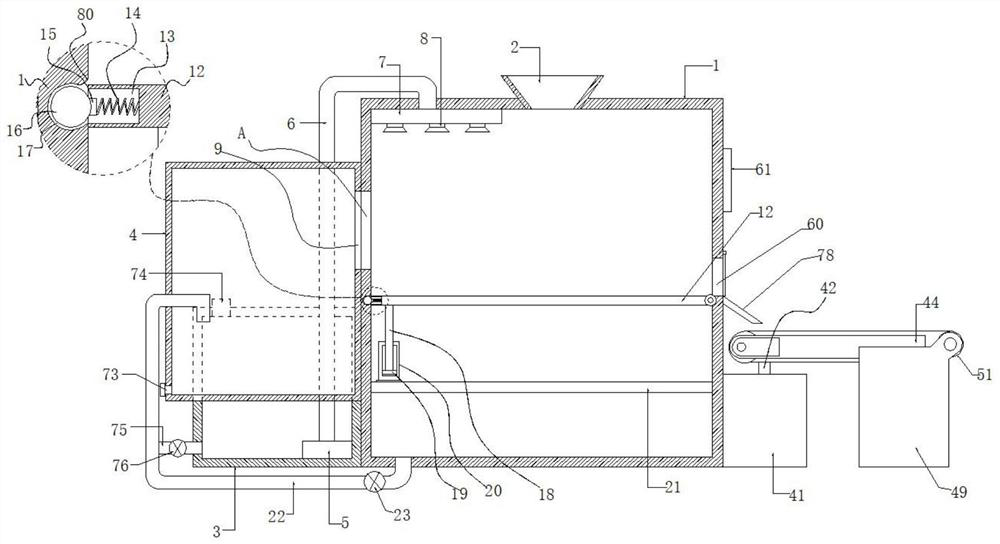
[0039] According to an embodiment of the present invention, an air-drying discharge device suitable for cleaning industrial parts is provided, such as Figure 1 to Figure 4 As shown, among them,

[0040] figure 1 It is a schematic diagram of the general structure of an air-drying discharge device for cleaning industrial parts according to an embodiment of the present invention, from figure 1 It can be seen from the figure that the cleaning tank 1, the w...


PUM


Abstract

The invention discloses an air-drying discharging device suitable for cleaning of industrial parts. The air-drying discharging device comprises a cleaning box, wherein a feeding port is formed in thecenter of the top of the cleaning box, and a water tank and a sewage collecting box are arranged at the side edge of the cleaning box; a water pump is placed in the water tank, and a water pumping pipe is connected to the water pump; the water pumping pipe penetrates through the water tank and extends to one side of the inner top of the cleaning tank; a water storage tank is formed in the water outlet end of the water pumping pipe and located on one side of the inner top of the cleaning tank, and a plurality of spray heads are arranged at the bottom of the water storage tank; a hole I is formed in the position, close to the upper part of the side edge of the cleaning tank, of the sewage collecting tank; a hollowed-out hole II is formed in the position, corresponding to the hole I, of the cleaning box; a lifting baffle is arranged in the hole II. Generated waste water can be collected to drive the air drying device to work, and generated wind energy facilitates air drying of the parts.Thus, the follow-up workload is reduced, and the parts can be effectively prevented from rusting.

Description

technical field [0001] The invention relates to the technical field of cleaning equipment, in particular to an air-drying discharge device suitable for cleaning industrial parts. Background technique [0002] After the parts are processed and packaged before leaving the factory, they need to be cleaned in order to clean the impurities or oil stains on the parts. In the traditional cleaning method, the parts to be cleaned are placed in the cleaning drum, and the parts are stirred. After the parts are cleaned, the waste water is discharged, and then the product is fished out of the water by the staff, and finally the product is put into the drying device. Drying, although this method can clean the parts, but after each cleaning, the worker needs to pick up the parts and move them to the drying device for drying, which increases the drying process and the labor of the workers. At the same time, the waste water produced after cleaning is directly discharged into the environment...

Claims


Application Information

Patent Timeline
Patent Type & Authority Applications(China)
IPC IPC(8): B08B3/02B08B3/14B08B13/00F26B21/00
CPCB08B3/02B08B3/14B08B13/00F26B21/001
Inventor 不公告发明人
Owner 薛浩然
Why Eureka
Try Eureka