
A thin-walled mold

A technology for thin-walled parts and molds, which is applied in the field of thin-walled parts molds, can solve the problems of adding shaping procedures, weak linkage ability, and low product yield, achieving consistent ejection and blowing, improving product quality, and saving processing the effect of time

Active Publication Date: 2021-10-15
苏州恒荣精密机电有限公司
View PDF0 Cites 0 Cited by
  • Summary
  • Abstract
  • Description
  • Claims
  • Application Information

AI Technical Summary

Problems solved by technology

[0003] Based on the demand for lightweight die-casting parts, thin-walled parts are the development trend. The defect of the current ejection method on the upper cover of die-casting thin-walled parts is that the force point of the product is opposite to the direction of ejection, resulting in low die-casting efficiency and cannot meet the delivery requirements. The demand for goods; the deformation of the product is uncontrollable, and it is necessary to increase the shaping process, which makes the process route longer; the appearance of the A-level surface is easy to bulge, or even top-through, and the product yield is not high; the thimble print needs to be removed by manpower or machining, which increases costs and wastes resources. ;Ejection needs to cooperate with blowing to complete the entire blanking process, blowing the material away from the processing range, but its own linkage ability is not strong, prone to discontinuous ejection and blowing, affecting efficiency

Method used


Image

  • A thin-walled mold
  • A thin-walled mold
  • A thin-walled mold

Examples


Embodiment Construction

[0023] In describing the present invention, it is to be understood that the terms "center", "upper", "lower", "front", "rear", "left", "right", "vertical", "horizontal", The orientations or positional relationships indicated by "top", "bottom", "inner", "outer", etc. are based on the orientations or positional relationships shown in the drawings, and are only for the convenience of describing the present invention and simplifying the description, rather than indicating or implying the It should not be construed as limiting the invention that a device or element must have a particular orientation, be constructed, and operate in a particular orientation.

[0024] In the description of the present invention, it should be noted that, unless otherwise specified and limited, the terms "installation", "connection", and "setting" should be understood in a broad sense, for example, it can be fixed connection, setting, or Removably attached, set, or integrally attached, set. Those of o...


PUM

PropertyMeasurementUnit
sizeaaaaaaaaaa

Abstract

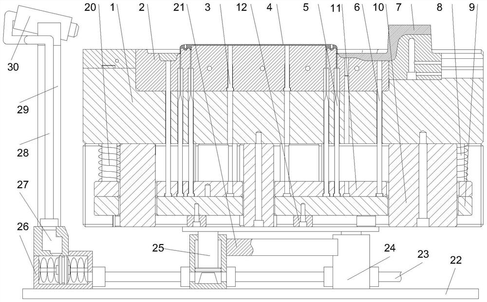
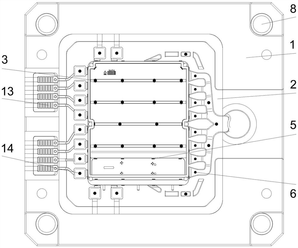
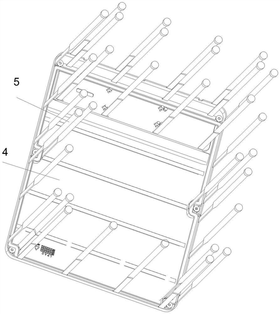
The invention discloses a mold for a thin-walled part, which mainly includes a main body, a mold core, an exhaust pin, a product, a flat ejector pin, a first auxiliary ejector pin, a bottom plate, a discharger and a second auxiliary ejector pin. The mold core is embedded and installed, and the top of the mold core is provided with a processing cavity. The top of the mold core is located at the processing cavity and the product is embedded. The edge of the product is provided with a material handle. First auxiliary thimble hole. The invention has a reasonable design in structure, the flat ejector pin is ejected, the product quality is improved, and the appearance is simple and beautiful; the post-processing time of polishing is saved, and the labor cost is reduced; weight reduction is optimized, mass production of thin-walled parts can be realized, and the practicability is high. Moreover, the continuity of ejection and blow-off of the discharge is good, and a reasonable and flexible structure is adopted to ensure the coherence of ejection and blow-off, and the angle of blow-off ensures a high success rate of blow-off.

Description

technical field [0001] The invention relates to a mold, in particular to a thin-wall mold. Background technique [0002] Mold, various molds and tools used in industrial production for injection molding, blow molding, extrusion, die-casting or forging forming, smelting, stamping and other methods to obtain the required products. In short, a mold is a tool used to make shaped objects. This tool is composed of various parts, and different molds are composed of different parts. It mainly realizes the processing of the shape of the article through the change of the physical state of the formed material. [0003] Based on the demand for lightweight die-casting parts, thin-walled parts are the development trend. The defect of the current ejection method on the upper cover of die-casting thin-walled parts is that the force point of the product is opposite to the direction of ejection, resulting in low die-casting efficiency and cannot meet the delivery requirements. The demand fo...

Claims


Application Information

Patent Timeline
Patent Type & Authority Patents(China)
IPC IPC(8): B22D17/22
CPCB22D17/2236
Inventor 瞿先明
Owner 苏州恒荣精密机电有限公司
Learn More