
Waste recovery device of wire cut electrical discharge machining machine tool

A wire cutting machine tool and waste recycling technology, applied in the field of machine tools, can solve problems such as affecting cutting, inconvenient cleaning, and increasing user workload, and achieve the effects of improving practicability, avoiding breakage, and improving work efficiency

Inactive Publication Date: 2021-02-19
泰州市江南机械制造有限公司
View PDF0 Cites 0 Cited by
  • Summary
  • Abstract
  • Description
  • Claims
  • Application Information

AI Technical Summary

Problems solved by technology

[0002] At present, according to the different wire-cutting methods of the wire-cutting machine tool, it can be divided into slow-feeding wire-cutting machine tools, medium-feeding wire-cutting machine tools and fast-feeding wire-cutting machine tools. The fast-moving wire-cutting machine tools have the advantages of simple structure, low cost, and less consumables during use Therefore, it is mass-produced and widely used in China. However, with the development of the national economy and the improvement of the technical level, a large amount of plastic waste and waste blocks will be produced in the process of cutting the workpiece. If it is not cleaned up in time, it will affect Cutting and cleaning are inconvenient. At the same time, the dust and large pieces of waste on the machine tool cannot be sorted and recycled, which will increase the workload of the user. Therefore, a waste recycling device for wire cutting machine tools is provided.

Method used


Image

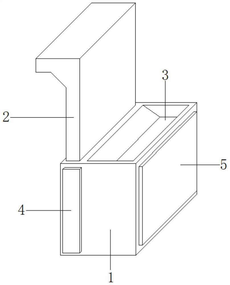
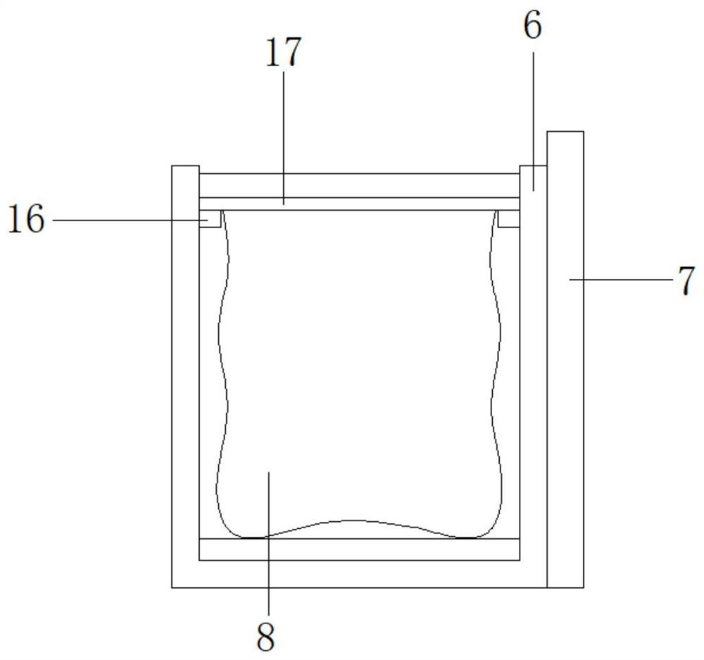
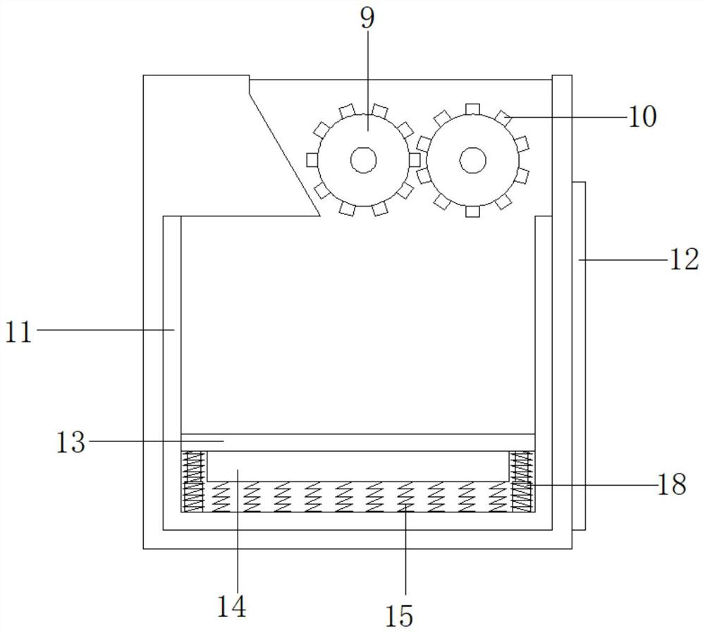
  • Waste recovery device of wire cut electrical discharge machining machine tool
  • Waste recovery device of wire cut electrical discharge machining machine tool
  • Waste recovery device of wire cut electrical discharge machining machine tool

Examples


Embodiment Construction

[0020] The preferred embodiments of the present invention will be described below in conjunction with the accompanying drawings. It should be understood that the preferred embodiments described here are only used to illustrate and explain the present invention, and are not intended to limit the present invention.

[0021] see Figure 1-3 , the present invention provides a technical solution: a waste recycling device for wire cutting machine tools, including a box body 1, a dust collection pipe 2 is connected through the top side of the box body 1 on the left side, and a dust collection pipe 2 is connected through the top side of the box body 1 on the right side. There is a feed port 3, and the front side of the box body 1 is movably connected with a dust collection box 4. By setting the dust collection pipe 2 and the dust collection box 4, the dust collection pipe 2 and the dust collection box 4 are connected through each other, and the dust collection The pipe 2 is mounted on...


PUM


Abstract

The invention relates to a waste recovery device of a wire cut electrical discharge machining machine tool. The waste recovery device of the wire cut electrical discharge machining machine tool comprises a box body, wherein a dust collecting pipe is connected to the left side of the top side of the box body in a penetrating mode, a feeding port is formed in the right side of the top of the box body in a penetrating mode, a dust collecting box is movably connected to the front side of the box body, and a waste collecting box is movably connected to the right side of the box body. The waste collecting box comprises a first box body and a first mounting plate, wherein the outer side of the first box body is fixedly connected with the first mounting plate, and a dust collecting bag is movablyconnected into an inner cavity of the first box body. Rotating rollers are symmetrically arranged between the inner walls of the box body, and cutting knife rings are arranged on the outer wall of each rotating roller at equal intervals. The waste recovery device of the wire cut electrical discharge machining machine tool can effectively conduct classified recovery of dust and large waste materials, the cleaning and recycling work efficiency of workers is greatly improved, the situation that the quantity of waste stored in the second box body is reduced due to the fact that the occupied spaceis large in the waste recycling and storing process is avoided, and the practicability of the whole device is greatly improved.

Description

technical field [0001] The invention relates to a waste recycling device for a wire cutting machine tool, which belongs to the technical field of machine tools. Background technique [0002] At present, according to the different wire-cutting methods of the wire-cutting machine tool, it can be divided into slow-feeding wire-cutting machine tools, medium-feeding wire-cutting machine tools and fast-feeding wire-cutting machine tools. The fast-moving wire-cutting machine tools have the advantages of simple structure, low cost, and less consumables during use Therefore, it is mass-produced and widely used in China. However, with the development of the national economy and the improvement of the technical level, a large amount of plastic waste and waste blocks will be produced in the process of cutting the workpiece. If it is not cleaned up in time, it will affect Cutting and cleaning are inconvenient, and at the same time, the dust and large pieces of waste on the machine tool c...

Claims


Application Information

Patent Timeline
IPC IPC(8): B26D7/18B02C4/08B02C4/30B02C4/42B02C18/14B02C18/18B02C18/24B02C23/00F16F15/067B29B17/04B23Q11/00
CPCB02C4/08B02C4/30B02C4/42B02C18/0092B02C18/142B02C18/18B02C18/24B02C23/00B23Q11/0067B26D7/18B26D2007/0018B29B17/04B29B2017/044B29B2017/0476F16F15/067Y02W30/62Y02P70/10
Inventor 俞俊王林
Owner 泰州市江南机械制造有限公司
Learn More