
Stall protection device for concrete stirring equipment

A mixing equipment and protection device technology, which is applied in the field of concrete, can solve problems such as insufficient mixing, stalling, and too fast rotation of the mixing rod, and achieve the effects of improving uniform mixing, ensuring stable work, and ensuring stable mixing

Active Publication Date: 2021-02-19
东台欣创混凝土制品有限公司
View PDF4 Cites 2 Cited by
  • Summary
  • Abstract
  • Description
  • Claims
  • Application Information

AI Technical Summary

Problems solved by technology

[0002] Concrete is a building material often used in construction. Concrete is mainly used to improve the strength of the building, ensure the stability of the building, and effectively improve the safety and quality of the building. At present, most of the concrete is produced by machinery, and the raw materials are added to the mixing equipment. In the process, it is stirred to fully mix the raw materials, but the current mixing device often has some problems when it is used, resulting in uneven mixing and affecting the quality of concrete.
[0003] When the current stirring device is in use, most of the stirring rods are driven by the motor to rotate. However, when the current motors are rotating, stalls often occur, causing the stirring rods to rotate too fast, stirring the raw materials to the outside of the mixing tank, making it difficult for the raw materials to Insufficient mixing, resulting in uneven mixing of the final concrete, which greatly reduces the quality of the concrete

Method used


Image

  • Stall protection device for concrete stirring equipment
  • Stall protection device for concrete stirring equipment
  • Stall protection device for concrete stirring equipment

Examples


Embodiment Construction

[0019] The following will clearly and completely describe the technical solutions in the embodiments of the present invention with reference to the accompanying drawings in the embodiments of the present invention. Obviously, the described embodiments are only some, not all, embodiments of the present invention. Based on the embodiments of the present invention, all other embodiments obtained by persons of ordinary skill in the art without making creative efforts belong to the protection scope of the present invention.

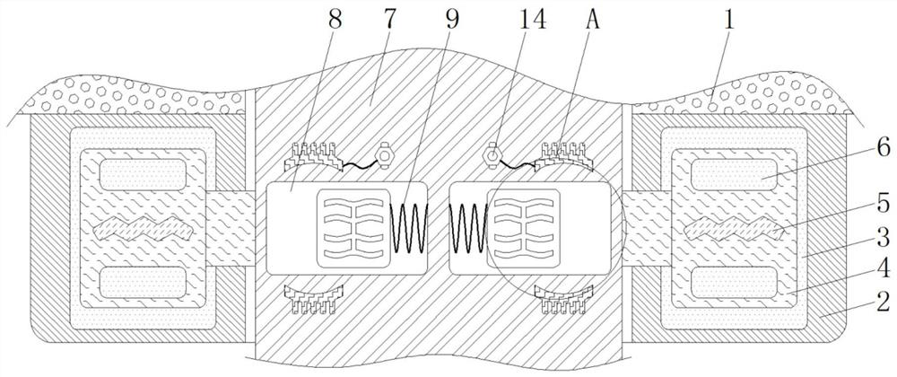
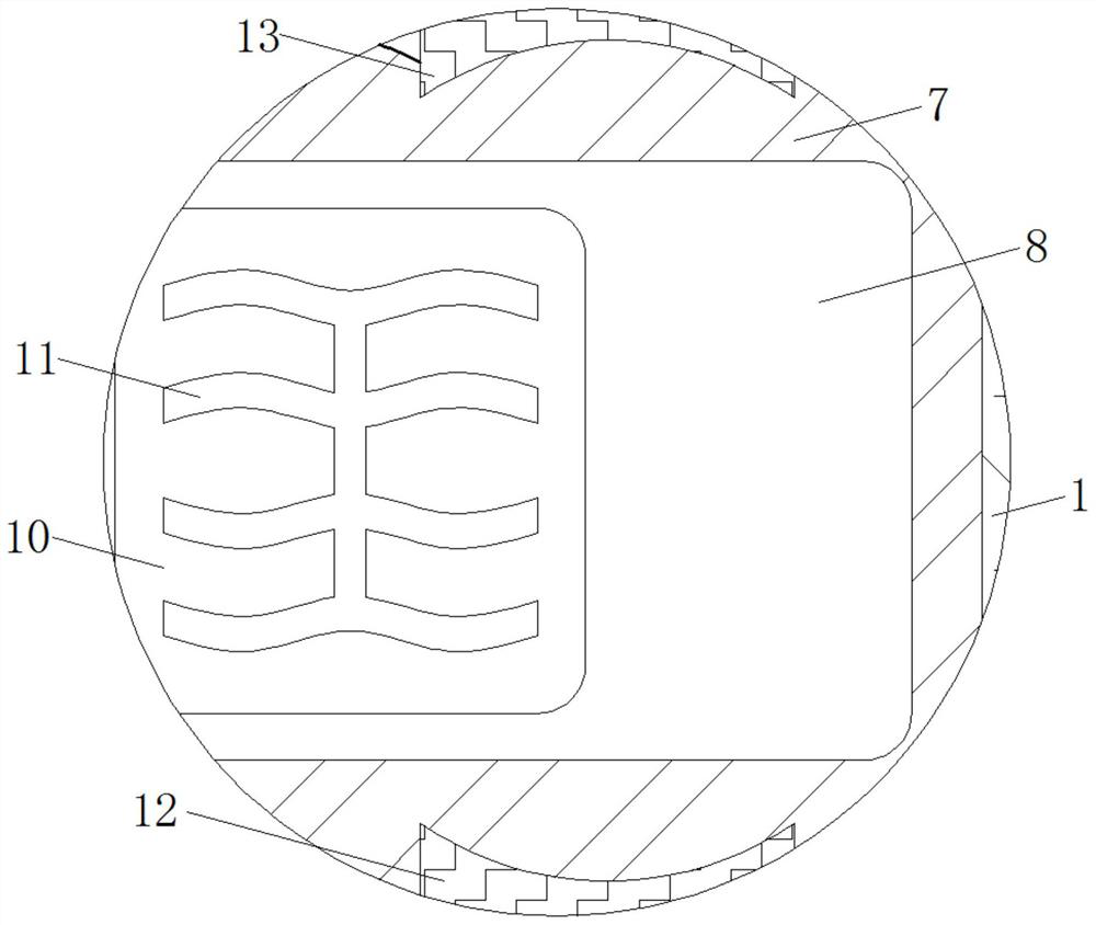
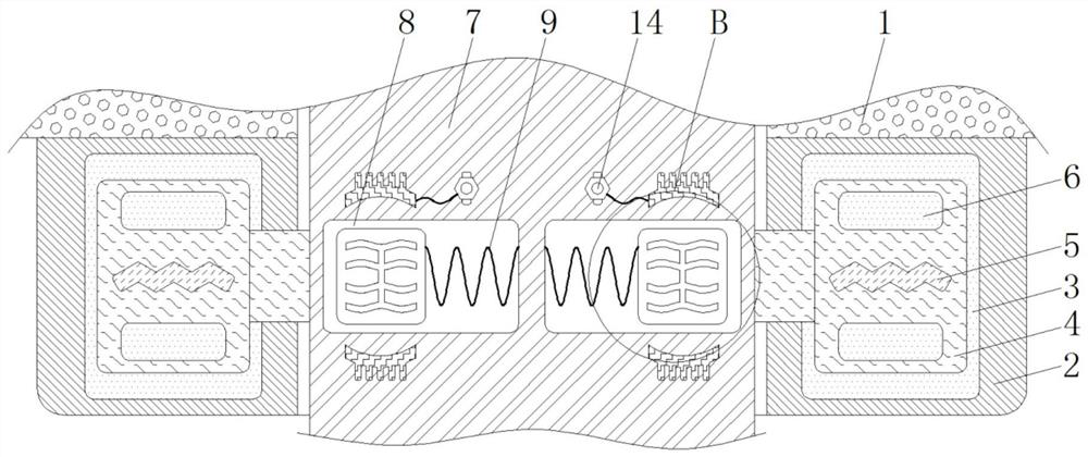
[0020] see Figure 1-4 , a stall protection device for concrete mixing equipment, including a housing 1, the material of the housing 1 is a hard high-strength material and the housing 1 does not have magnetic conductivity and electrical conductivity, and the housing 1 plays the role of fixing various components, The material of the fixed seat 2 is a hard high-strength material and the shape of the fixed seat 2 is circular. The fixed seat 2 plays the role of fi...


PUM


Abstract

The invention relates to a stall protection device for concrete stirring equipment, and relates to the technical field of concrete. The stall protection device for the concrete stirring equipment comprises a shell, wherein a fixed seat is fixedly connected to the bottom of the shell; a circular ring is arranged in the middle of the fixed seat; uniformly distributed rotating blocks are movably connected to the inner wall of the circular ring; electromagnets are fixedly connected to the inner walls of the rotating blocks; damping holes are formed in the inner walls of the rotating blocks; stirring rods penetrating through the fixed seat are fixedly connected to the inner sides of the rotating blocks; and two symmetrical sliding grooves are formed in the inner wall of each stirring rod. According to the stall protection device for the concrete mixing equipment, through cooperative use of the electromagnets and the rotating blocks, when the rotating speed of the stirring device is too high, the electromagnets are in a power-on state at the moment, the viscosity of magnetorheological fluid in the circular ring is increased at the moment, and the magnetorheological fluid in the damping holes is difficult to flow at the moment, so that the rotating speed of the rotating blocks is effectively reduced, the rotating speed of the stirring rods is further reduced, stable stirring of the stirring device is guaranteed, and the uniform mixing degree of concrete is improved.

Description

technical field [0001] The invention relates to the technical field of concrete, in particular to a stall protection device for concrete mixing equipment. Background technique [0002] Concrete is a kind of building material often used in construction. Concrete is mainly used to improve the strength of the building, ensure the stability of the building, and effectively improve the safety and quality of the building. Most of the current concrete is produced by machinery, and the raw materials are added to the mixing equipment. In the mixing process, it is stirred to fully mix the raw materials, but the current mixing device often has some problems when it is used, resulting in uneven mixing and affecting the quality of the concrete. [0003] When the current stirring device is in use, most of the stirring rods are driven by the motor to rotate, but when the current motors are rotating, stalls often occur, causing the stirring rod to rotate too fast, stirring the raw materials...

Claims


Application Information

Patent Timeline
IPC IPC(8): B28C5/08
CPCB28C5/0806B28C5/0831
Inventor 刘慧
Owner 东台欣创混凝土制品有限公司
Learn More