Rubber powder magnetic separation system and magnetic separation method

A rubber powder and magnetic separation technology, applied in the field of rubber powder, can solve the problems of wasting metal resources, clogging, increasing the cost of rubber powder magnetic separator, etc., and achieve the effect of reducing the frequency of cleaning

Inactive Publication Date: 2021-02-19
佛山中易德化工材料有限公司
View PDF0 Cites 0 Cited by
  • Summary
  • Abstract
  • Description
  • Claims
  • Application Information

AI Technical Summary

Problems solved by technology

[0004] 1. Since the existing rubber powder magnetic separator can only perform a magnetic separation on the rubber powder made of waste tires, and the same batch of rubber powder only undergoes magnetic separation once in the current process, resulting in Metal powder is easy to remain in the rubber powder after magnetic separation, which makes the effect of magnetic separation of rubber powder by the existing rubber powder magnetic separator poor, reduces the subsequent use effect of rubber powder in the process of use, and wastes metal resources;
[0005] 2. The filter hole on the rubber powder magnetic separator is easy to be blocked by metal powder and rubber powder when the rubber powder made of waste tires is magnetically separated, so the rubber powder magnetic separator needs to be cleaned frequently, which increases the impact on the rubber powder magnetic separator. The cost of machine selection for maintenance

Method used


Image

  • Rubber powder magnetic separation system and magnetic separation method
  • Rubber powder magnetic separation system and magnetic separation method
  • Rubber powder magnetic separation system and magnetic separation method

Examples


Embodiment Construction

[0037] In order to make the technical means, creative features, goals and effects achieved by the present invention easy to understand, the present invention will be further described below in conjunction with specific illustrations. It should be noted that, in the case of no conflict, the embodiments in the present application and the features in the embodiments can be combined with each other.

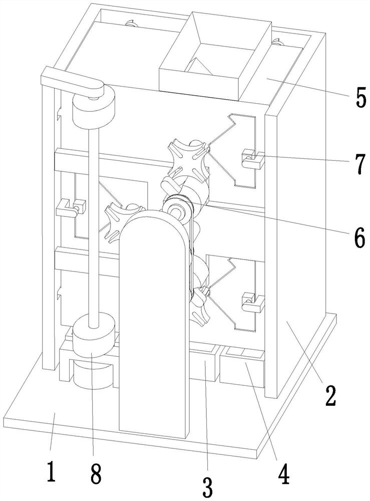
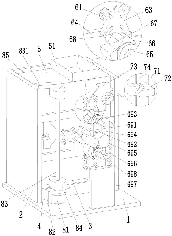
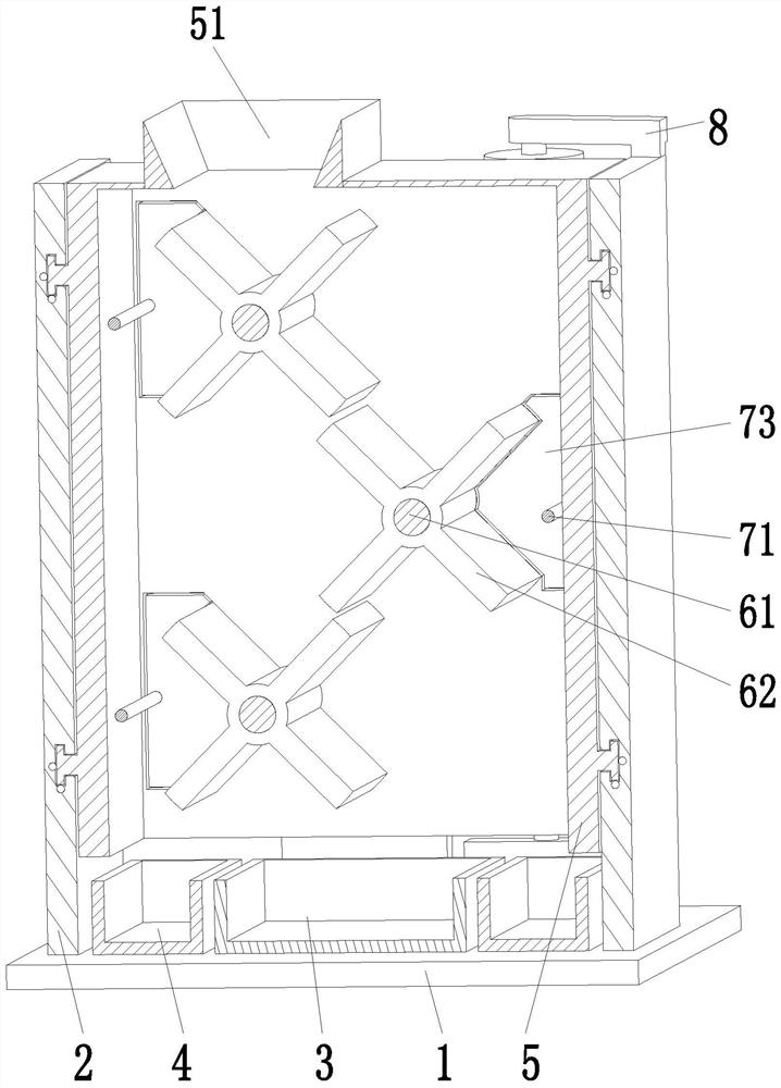
[0038] like Figure 1 to Figure 5 As shown, a rubber powder magnetic separation system includes a base 1, a yoke-shaped plate 2, a rubber collection box 3, a metal collection box 4, a magnetic separation box 5, a magnetic separation mechanism 6, a cleaning mechanism 7 and a shaking mechanism 8, and the base 1. A 匚-shaped plate 2 is installed on the rear side of the upper end surface. The 匚-shaped plate 2 is a 匚-shaped structure. The middle part of the upper end surface of the base 1 is located on the inner side of the 匚-shaped plate 2. A rubber collection box 3 is installed, and the ...


PUM


Abstract

The invention relates to a rubber powder magnetic separation system and a magnetic separation method. The rubber powder magnetic separation system comprises a base, a [-shaped plate, a rubber collection box, metal collection boxes, a magnetic separation box, a magnetic separation mechanism, a material cleaning mechanism and shaking mechanisms, wherein the [-shaped plate is arranged on the rear side of the upper end face of the base; the rubber collection box is arranged in the middle of the upper end face of the base; the metal collecting boxes are symmetrically arranged on the left side and the right side of the upper end face of the base; a magnetic separation box is arranged on the inner side of the [-shaped plate and located at the upper end of the rubber collecting box in a front-backsliding fit mode; a feeding groove is formed in the right side of the upper end face of the magnetic separation box; a magnetic separation mechanism is arranged in the magnetic separation box; the material cleaning mechanism is arranged at the position, located outside the magnetic separation mechanism, in the magnetic separation box; and the shaking mechanisms are arranged on the front side andthe rear side of the magnetic separation box. According to the rubber powder magnetic separation system and the magnetic separation method provided by the invention, the problems that in the prior art, in the process that a rubber powder magnetic separator is used for conducting magnetic separation operation on rubber powder made of waste tires, the effect of conducting magnetic separation on therubber powder is poor, the rubber powder magnetic separator needs to be cleaned frequently, and the like are solved.

Description

technical field [0001] The invention relates to the technical field of rubber powder, in particular to a rubber powder magnetic separation system and a magnetic separation method. Background technique [0002] With the gradual improvement of people's living standards and the rapid development of the logistics industry, the number of private cars and trucks in my country has increased year by year. The increase in the number of vehicles has driven economic development. At the same time, the consumption and wear of automobile tires have also produced a lot of waste tires. A few years ago, waste tires were thrown away as garbage, which greatly polluted the environment we depend on for survival. Later, the waste tire recycling industry quietly emerged. After waste tire recycling, it can be used in: a. Sports ground laying: such as Runways, school playgrounds, etc.; b. Automobile industry: strips, train floor mats, sealing strips, buffers, shock absorbers, tires and tire inner pads...

Claims


Application Information

Patent Timeline
Patent Type & Authority Applications(China)
IPC IPC(8): B29B17/02B03C1/02
CPCB03C1/02B29B17/02B29B2017/0272Y02W30/52Y02W30/62
Inventor 不公告发明人
Owner 佛山中易德化工材料有限公司
Why Eureka
Try Eureka