Magnetic separator

A magnetic separator and magnet technology, applied in the field of magnetic separators, can solve the problems of manual cleaning, large volume, complex structure, etc., and achieve the effect of improving efficiency, improving magnetic separation effect, and simple structure

Inactive Publication Date: 2013-04-03
溧阳市华生机械制造有限公司
View PDF1 Cites 4 Cited by
  • Summary
  • Abstract
  • Description
  • Claims
  • Application Information

AI Technical Summary

Problems solved by technology

Its main disadvantage: need to manually clean up the adsorbed iron impurities
Its main shortcomings: complex structure, large volume

Method used


Image

  • Magnetic separator
  • Magnetic separator

Examples


Embodiment

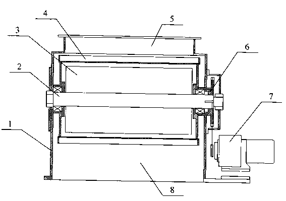
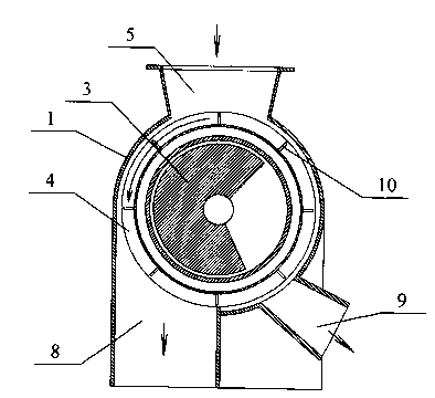
[0018] Such as figure 1 with figure 2 As shown, a magnetic separator includes a magnet 3, a feed port 5 and a discharge port, and also includes an organic base 1, a fixed shaft 2, a magnet 3, a drum 4, a feed port 5, a driving wheel 6 and a motor 7 . The discharge port is composed of a first discharge port 8 and a second discharge port 9 . The top of the machine base 1 is provided with a material inlet 5 , and the lower end of the machine base 1 is provided with a first material outlet 8 and a second material outlet 9 . The fixed shaft 2 is fixedly connected with the machine base 1, the fixed shaft 2 is connected with the rotating drum 4 through the bearing, the magnet 3 is located between the rotating drum 4 and the fixed shaft 2 and is connected with the fixed shaft 2, and the rotating drum 4 is not in contact with the magnet 3. The power output end of the motor 7 is connected with the driving wheel 6, and the driving wheel 6 is connected with the power input end of the ...


PUM


Abstract

The invention particularly relates to a magnetic separator comprising a magnet (3), a feed port (5), a stand (1), a fixed shaft (2), the magnet (3), a rotary drum (4), the feed port (5), a motor (7), a first discharge port (8) and a second discharge port (9), wherein the feed port (5) is positioned at the top end of the stand (1); and the first discharge port (8) and the second discharge port (9) are positioned at the lower end of the stand (1). The fixed shaft (2) is fixedly connected with the stand (1), the fixed shaft (2) is connected with the rotary drum (4) by a bearing, the magnetic (3) is positioned between the rotary drum (4) and the fixed shaft (2) and is connected with the fixed shaft (2), a power output end of the motor (7) is connected with a power input end of the rotary drum (4), a section of the magnet (3) is a sector magnet extending to the first discharge port (8) from the feed port (5), and the second discharge port (9) is positioned on the rear side of the sector magnet. By utilizing the magnetic separator, iron impurities can be automatically cleared, and the magnetic separation effect is good.

Description

technical field [0001] The invention relates to a device for magnetic separation using permanent magnets, in particular to a magnetic separator. The invention is suitable for magnetic separation and cleaning of iron impurities in materials, and belongs to the technical field of mechanical equipment manufacturing and processing. Background technique [0002] The permanent magnetic cylinder magnetic separator consists of two parts, the inner cylinder and the outer cylinder, which are connected to the conveying pipeline through the upper and lower flanges. The inner cylinder is the magnet, which is assembled by several permanent magnets and magnetic plates, that is, copper screws fixed on the magnetic plate. There is a smooth and wear-resistant stainless steel outer cover outside the magnet, which is fixed on the outer cylinder door with a steel belt, and the outer cylinder door can be opened when cleaning the iron absorbed by the magnet. [0003] Chinese Patent No. ZL200820...

Claims


Application Information

Patent Timeline
Patent Type & Authority Applications(China)
IPC IPC(8): B03C1/14
Inventor 耿福生耿震华
Owner 溧阳市华生机械制造有限公司
Why Eureka
Try Eureka