High-efficiency complex ore-dressing device and ore dressing method

A compound and efficient technology, applied in chemical instruments and methods, wet separation, solid separation, etc., can solve the problems of poor sorting effect, large floor space, long process flow, etc., to improve the strength and depth of the magnetic field , Reduce floor space and shorten the process flow

Active Publication Date: 2015-04-08
石家庄金垦科技有限公司
View PDF7 Cites 5 Cited by
  • Summary
  • Abstract
  • Description
  • Claims
  • Application Information

AI Technical Summary

Problems solved by technology

For fine-grained refractory ore, the grinding fineness is large, and the volume difference, magnetic difference, quality difference, and water buoyancy difference between impurities and magnetic mineral particles will all become smaller, resulting in poor separation effect
Sometimes it is necessary to simply connect multiple elutriation machines and magnetic flotation columns in series to form a system to realize the separation of iron ore. There are technical problems such as large area occupation, long process flow and high cost.

Method used


Image

  • High-efficiency complex ore-dressing device and ore dressing method
  • High-efficiency complex ore-dressing device and ore dressing method
  • High-efficiency complex ore-dressing device and ore dressing method

Examples


Embodiment 1

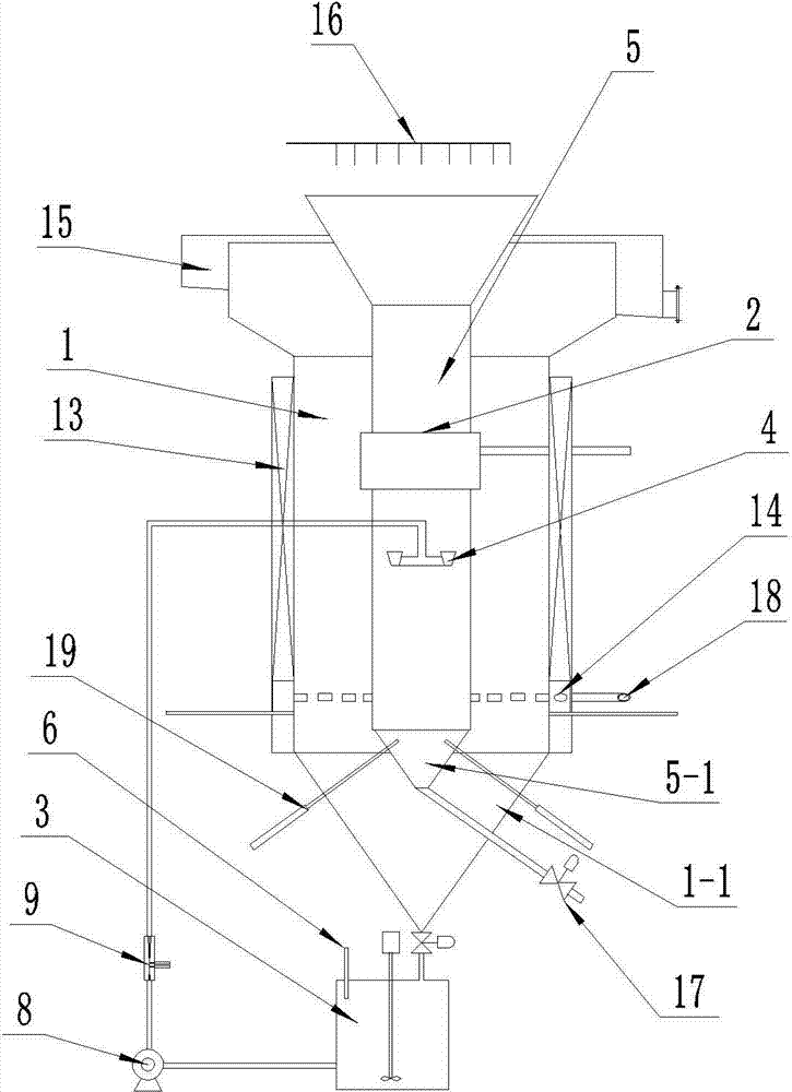
[0026] Example one, see attached figure 1 , The elutriator feeder 2 is arranged along the circumferential direction of the magnetic flotation column 5. The magnetic flotation column 5 is entirely located in the cavity of the washing machine 1, and a return mechanism is provided between the washing machine 1 and the magnetic flotation column 5. The return mechanism includes a stirring tank 3 with a dosing port 6, a slurry pump 8 and an air jet 9 connected in series. The discharge port of the elutriation machine 1 is connected with a stirring tank 3 arranged outside. The stirring tank 3 is provided with a dosing port 6, and the stirring tank 3 is equipped with a stirring device. The discharge port of the stirring tank 3 passes through a slurry pump 8 The air jet 9 is connected to the magnetic flotation column feeder 4 arranged in the magnetic flotation column 5. The feeding height of the magnetic flotation column feeder 4 is 1 / 3-1 / 2 of the height direction of the elutriator 1 to...

Embodiment 2

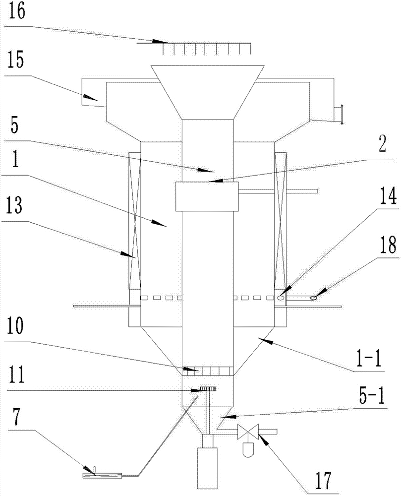
[0032] Example two, see attached figure 2 The difference from the structure in the first embodiment is that the magnetic flotation column 5 penetrates the washing machine 1 and the discharge port of the washing machine 1 is the slurry flow inlet 10 at the connection part of the magnetic flotation column 5 and the washing machine 1. The return mechanism is a coarse concentrate drop hopper 1-1 with a lower port positioned at the lower end of the magnetic flotation column 5, and a passage between the annular cavity of the elutriator 1 and the inner cavity of the magnetic flotation column 5 is formed by the coarse concentrate port 10. Inside the magnetic flotation column 5 and below the coarse concentrate port 10, a stirrer 11 and its driving mechanism are arranged. The lower section of the magnetic flotation column 5 and below the coarse concentrate port 10 are provided with a jet 7, and the jet 7 is provided with a gas injection port and Dosing port; at the end of the magnetic fl...

Embodiment 3

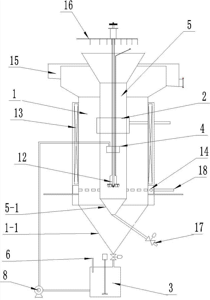
[0038] Example three, see attached image 3 The difference from the first embodiment is that the coarse concentrate washed by the washing machine 1 is directly fed into the magnetic flotation column 5 by the slurry pump 8. The return mechanism includes a slurry pump 8. The stirring device 12 pulverizes the air sent from the gas pipe to the lower end of the flotation column 5 into micro-bubbles and fully mixes with the slurry for mineralization. Preferably, the stirring device 12 is arranged coaxially with the magnetic flotation column 5.

[0039] When working, the specific beneficiation methods are as follows:

[0040] 1. The excitation coil 13 supplies magnetism to the washing machine 1, the water inlet pipe 18 feeds water to the washing machine 1 through the water feeder 14, and the slurry is evenly formed by the washing machine 1 and the magnetic flotation column 5 through the feeder 2 of the washing machine. The material is fed in the annular cavity. Under the combined action ...


PUM


Abstract

The invention belongs to the technical field of mineral separation, provides a high-efficiency complex ore-dressing device and a high-efficiency ore dressing method, and solves the technical problem that existing wash mills and magnetic flotation columns are high in space occupancy and long in technical process for iron ore dressing. The high-efficiency complex ore-dressing device structurally comprises cylinders of a wash mill and a magnetic flotation column, feeding and discharging passages and a servo mechanism, and the feeding and discharging passages are fittingly matched with the two cylinders. The high-efficiency complex ore-dressing device is characterized in that the cylinders of the wash mill and the magnetic flotation column are in a coaxial nested complex structure, and excitation coils are arranged outside the wash mill with an annular section. The high-efficiency complex ore-dressing device and the high-efficiency ore dressing method have the advantages that technical process is effectively shortened, floor area is greatly reduced, and high economic benefits can be obtained.

Description

Technical field [0001] The invention belongs to the technical field of mineral separation, and particularly relates to a composite ore dressing device and a ore dressing method with short process flow, small footprint, high separation efficiency, and low device production cost. Background technique [0002] In the field of mining and metallurgical production, the beneficiation device is an important production equipment. Flotation and magnetic separation are two important methods of beneficiation. The current beneficiation devices are all structural designs based on their own mechanisms. In view of the limitations of the two mechanisms, in actual production practice, independent flotation or magnetic separation equipment is often combined in series to form a system to make up for the deficiencies of a single device. [0003] Iron ore, especially the hard-to-select minerals such as poor, fine, and miscellaneous, is suitable for magnetic separation. At present, fine grinding and c...

Claims


Application Information

Patent Timeline
Patent Type & Authority Applications(China)
IPC IPC(8): B03B7/00
CPCB03B7/00
Inventor 王青智晓康魏吉辰
Owner 石家庄金垦科技有限公司
Why Eureka
Try Eureka