Oil refining wastewater oil stain separation device utilizing air flotation method

A technology for separation of oil refining wastewater and oil pollution, applied in flotation water/sewage treatment, grease/oily substance/float removal device, water/sewage treatment, etc. Reasonable structure, strong practicability, and the effect of enhancing the collection speed

Inactive Publication Date: 2021-02-19
WUXI GONGYUAN MACHINERY
View PDF3 Cites 3 Cited by
  • Summary
  • Abstract
  • Description
  • Claims
  • Application Information

AI Technical Summary

Problems solved by technology

[0003] A lot of waste water will be produced in the oil refining process, which often contains a lot of oil impurities. If these oil impurities are not treated and discharged directly into the natural environment, it will not only pollute the environment, but may also cause pollution after being drunk by people. Physical discomfort may cause harm to the human body in severe cases. At present, people also use some devices to separate and purify the oil in the refinery wastewater
[0004] However, in the actual use process, the existing refinery wastewater oil pollution separation device can basically separate the oil pollution in the wastewater, but it is difficult to collect and separate solid impurities such as sand in the wastewater, and the practicability is poor.

Method used


Image

  • Oil refining wastewater oil stain separation device utilizing air flotation method
  • Oil refining wastewater oil stain separation device utilizing air flotation method
  • Oil refining wastewater oil stain separation device utilizing air flotation method

Examples


Embodiment 1

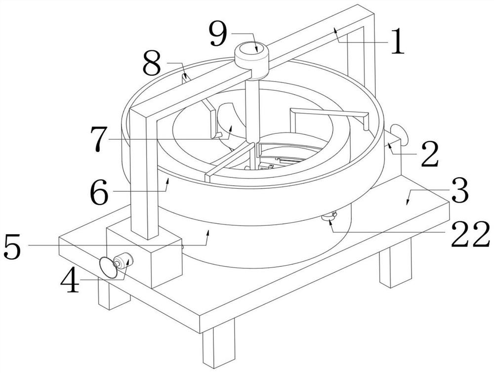
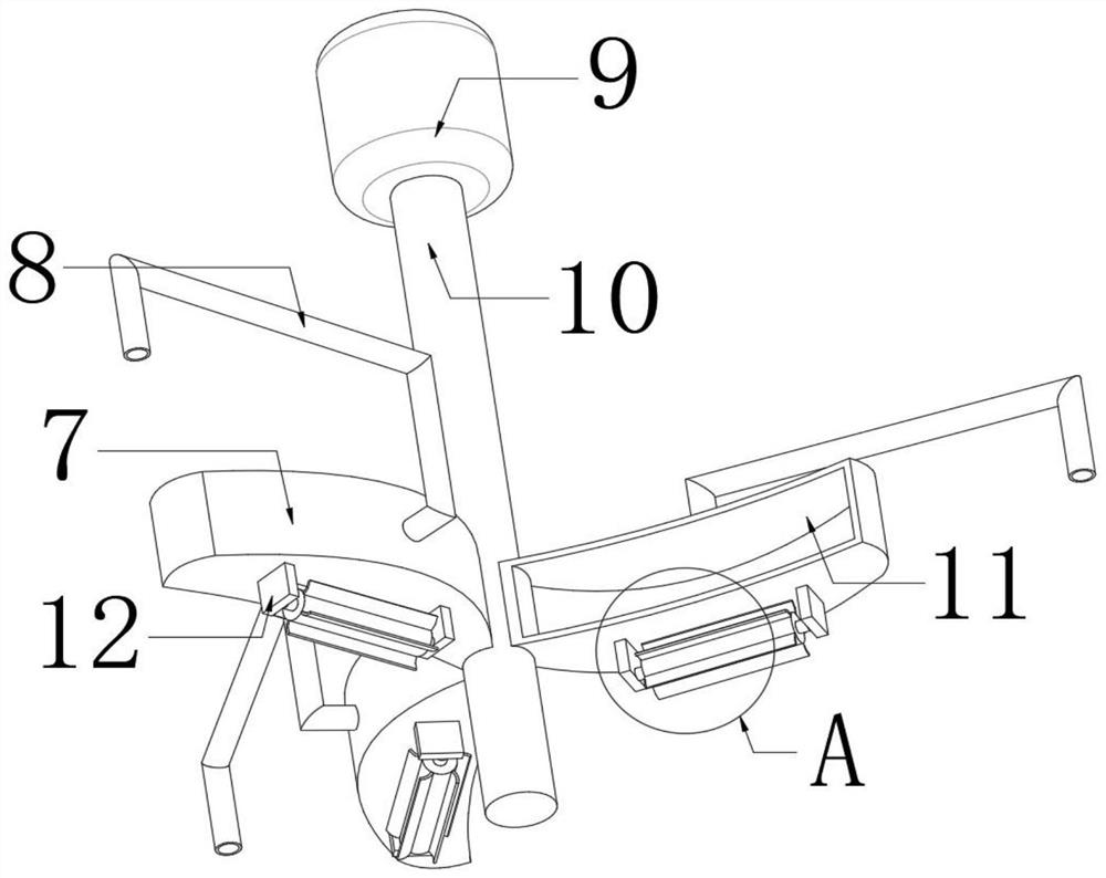
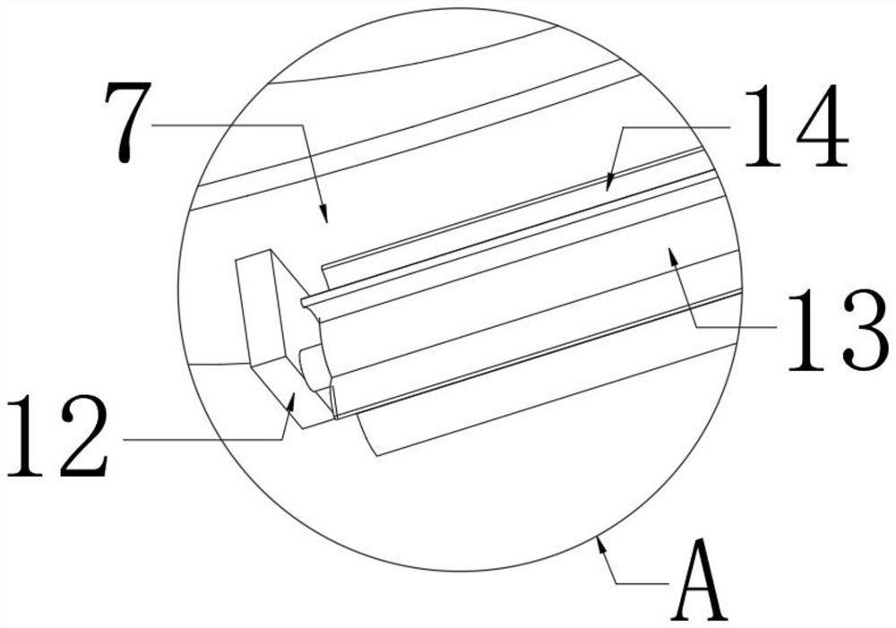
[0028] refer to Figure 1-4 , a kind of refinery wastewater oil separation device utilizing air flotation method, comprising a workbench 3, the top outer wall of the workbench 3 is fixed with a separation cylinder 5 by bolts, the bottom inner wall of the separation cylinder 5 is fixed with an air bag 17 by bolts, and the top of the air bag 17 is The outer wall is provided with air outlets distributed equidistantly, and the inner wall of the air outlet is plugged with an air outlet pipe 19, and both sides of the outer wall of the top of the workbench 3 are provided with an air intake mechanism, and the top outer wall of the air intake mechanism is provided with a cross bar 1, and the cross bar The outer wall of the top of 1 is fixed with a motor 9 by bolts, and the output shaft of the motor 9 is connected with a rotating rod 10 through a coupling. The outer wall is fixed with a mounting plate 12 by bolts, and the outer wall of the mounting plate 12 is connected with a rotating ...

Embodiment 2

[0038] refer to Figure 5 , a kind of refinery wastewater oil separation device utilizing air flotation method, comprising a workbench 3, the top outer wall of the workbench 3 is fixed with a separation cylinder 5 by bolts, the bottom inner wall of the separation cylinder 5 is fixed with an air bag 17 by bolts, and the top of the air bag 17 is The outer wall is provided with air outlets distributed equidistantly, and the inner wall of the air outlet is plugged with an air outlet pipe 19, and both sides of the outer wall of the top of the workbench 3 are provided with an air intake mechanism, and the top outer wall of the air intake mechanism is provided with a cross bar 1, and the cross bar The outer wall of the top of 1 is fixed with a motor 9 by bolts, and the output shaft of the motor 9 is connected with a rotating rod 10 through a coupling. The outer wall is fixed with a mounting plate 12 by bolts, and the outer wall of the mounting plate 12 is connected with a rotating ro...


PUM


Abstract

The invention belongs to the technical field of oil stain separation, particularly relates to an oil refining wastewater oil stain separation device utilizing an air flotation method, and provides thefollowing scheme aiming at the problems that an existing oil refining wastewater oil stain separation device can basically separate oil stains in wastewater, but solid impurities such as sand grainsin the wastewater are difficult to collect and separate. The device comprises a workbench, a separation cylinder is fixed to the outer wall of the top of the workbench through bolts, an air bag is fixed to the inner wall of the bottom of the separation cylinder through bolts, air outlet holes distributed at equal intervals are formed in the outer wall of the top of the air bag, and air outlet pipes are inserted into the inner walls of the air outlet holes. The slag scraping hopper can drive the rotating roller and the stirring blades to rotate while rotating, the stirring blades can further stir sand grains in waste water while rotating, accordingly, the sand grain collecting speed of the filtering net bag can be increased, and people can take down the filtering net bag through the fixingbuckles to treat solid impurities in the net bag after separation is completed.

Description

technical field [0001] The invention relates to the technical field of oil and dirt separation, in particular to an oil refining wastewater oil and dirt separation device using an air flotation method. Background technique [0002] The air flotation method refers to the use of highly dispersed micro-bubbles as a carrier to adhere to the pollutants in the wastewater, making their buoyancy greater than gravity and buoyancy resistance, so that the pollutants float to the water surface to form foam, and then scraped from the water surface with slag scraping equipment The process of removing foam and realizing solid-liquid or liquid-liquid separation is called air flotation. The necessary conditions for the air flotation process are: in the treated wastewater, a large number of fine air bubbles should be distributed, and the treated pollutants should be in a suspended state, and the surface of the suspended particles should be hydrophobic, easy to adhere to the air bubbles and fl...

Claims


Application Information

Patent Timeline
Patent Type & Authority Applications(China)
IPC IPC(8): C02F9/02C02F103/36
CPCC02F9/00C02F1/24C02F1/40C02F1/38C02F1/001C02F2103/365C02F2201/002C02F2201/004C02F2303/14C02F2303/16
Inventor 黄俊波汪日平
Owner WUXI GONGYUAN MACHINERY
Why Eureka
Try Eureka