Triangular electromagnet unit

A triangular, electromagnet technology, applied in the electromagnetic field, can solve problems such as difficult to reflect the effect of magnetic concentration and enhance the magnetic effect, and achieve the effect of uniform increase, high versatility, and obvious enhancement effect

Pending Publication Date: 2021-02-19
苏州英磁新能源科技有限公司
View PDF1 Cites 0 Cited by
  • Summary
  • Abstract
  • Description
  • Claims
  • Application Information

AI Technical Summary

Problems solved by technology

However, for a special-shaped electromagnetic unit with multiple surfaces, it only realizes the basic magnetic force generation, and it is difficult to reflect the effect of magnetic concentration and the effect of enhancing the magnetic force on one side.

Method used


Image

  • Triangular electromagnet unit
  • Triangular electromagnet unit
  • Triangular electromagnet unit

Examples


Embodiment 1

[0039]The triangular electromagnet includes a triangular prism-shaped body. Spiral coils are respectively wound on the three sides, and the cross section formed by the three sides is triangular. Wherein, the two sides are two triangular sides, and the first spiral coil and the second spiral coil are respectively wound on the two sides. The parallel coil that generates the vertical magnetic field is the first solenoid, the vertical coil that generates the parallel magnetic field is the second solenoid, and the tilted coil that generates the gradient magnetic field is the third solenoid.

[0040]The first spiral coil and the second spiral coil form a magnetic field perpendicular to the current flow plane and the direction of the magnetic force towards the inside of the triangle after being energized. Then, the third solenoid is wound on the third side between the two sides. After the third solenoid is energized, a magnetic field is generated perpendicular to the side surface and the dire...

Embodiment 2

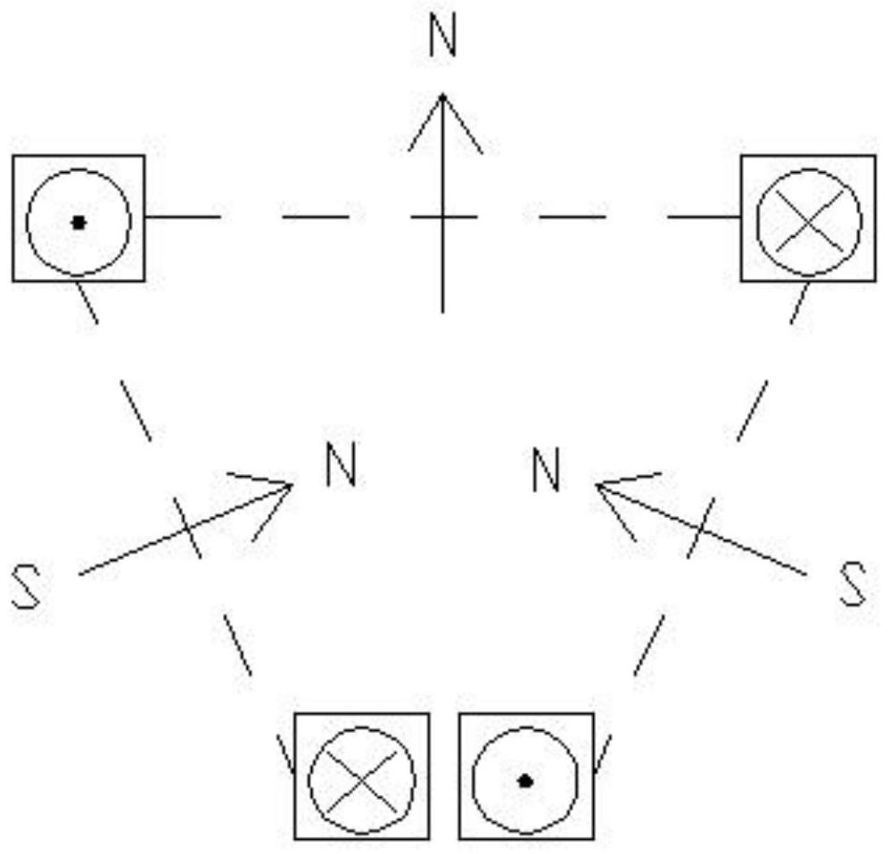
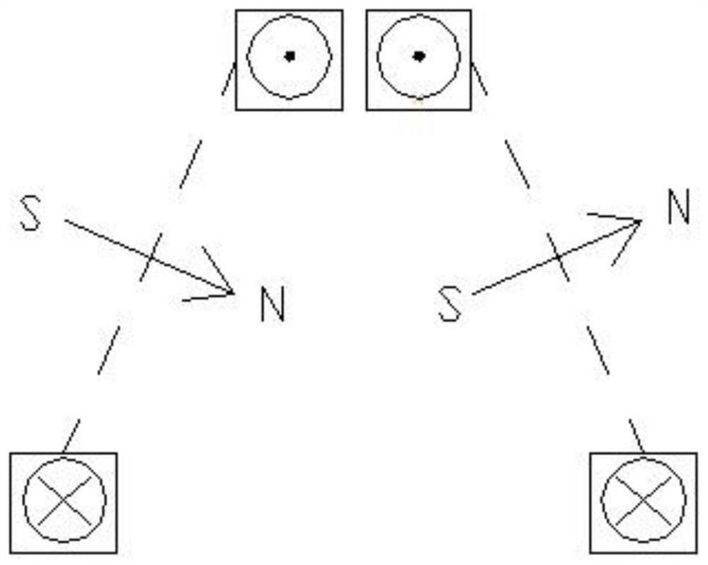
[0067]With the electromagnet center unit in Embodiment 1, the unit arrangement of the Halbach array on the left and right sides can further enhance the magnetic force on one side.

[0068]Therefore, the side units on both sides serve as the magnetic increase of the sides of the adjacent central unit. Such asfigure 2 As shown, due to the triangular array relationship, only two sides of the side unit have magnetic force. The side unit on the left side of the center unit generates a magnetic field in the same direction as the magnetic force of the side solenoid on the left side of the center unit. Both sides of the side unit generate magnetic fields in this direction to form a continuous magnetic field "continuous" increase (ie. In the figure, the two magnetic field directions on the left unit are counterclockwise). In the same way, the side unit on the right side of the center unit generates a magnetic field in the same direction as the magnetic force generated by the solenoid on the rig...

Embodiment 3

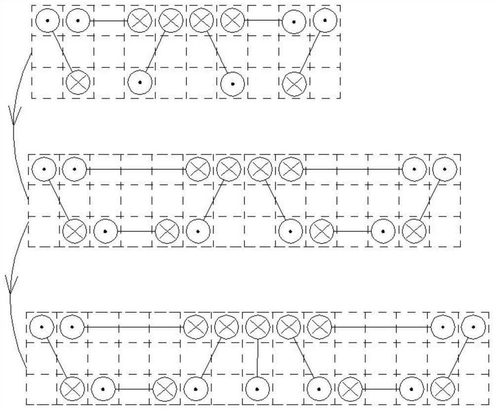
[0071]Such asimage 3 As shown, from the grid-like arrangement relationship, the arrangement order of the array can be clearly seen.

[0072]Fromimage 3 As can be seen from the wire nodes in the arrangement, the connection relationship of the spiral coils in this arrangement can be connected in series, and the coiled wires can be arranged reasonably to meet the requirements of forming the magnetic field in the desired direction; parallel connection can also be used, namely Connecting the two spiral coils in parallel leads out. The series connection method can reduce the loss, but the circuit arrangement is more complicated.

[0073]The electromagnetic unit in the middle position can form a magnetic field that is perpendicular to the horizontal plane and the direction of the magnetic force is upward, and the spiral coils on the side surfaces of the two sides of the electromagnetic unit are perpendicular to the surface and enhance the magnetic field of the upward magnetic field.

[0074]There i...


PUM


Abstract

The invention discloses a triangular electromagnet unit. The triangular electromagnet unit comprises an electrified solenoid coil, and the solenoid coil forms a magnetic field perpendicular to a current flowing plane after being electrified, and comprises a first solenoid coil which is electrified to form a first magnetic field; a second solenoid coil which is electrified to form a second magneticfield; or a third solenoid coil which is electrified to form a third magnetic field. The third magnetic field is a magnetic field with magnetic lines facing the outside of the plane of the third solenoid coil, and the three solenoid coils are arranged in a manner that the cross sections formed by intersecting the planes where the three solenoid coils are located in pairs are triangular. When thethird magnetic field is generated, the first magnetic field and the second magnetic field arrange the current flow direction according to magnetic field setting that magnetic lines face the center ofthe triangular cross section; and if the third magnetic field does not occur, the first magnetic field and the second magnetic field arrange the current flow direction according to the magnetic fieldsetting with the same magnetic line side directions. According to the scheme, the electromagnets are used for replacing permanent magnets, the same purpose is achieved, and the production and machining cost is reduced.

Description

Technical field[0001]The invention relates to the field of electromagnetic technology, in particular to a triangular electromagnet unit.Background technique[0002]Electromagnet is a device that generates electromagnetism when energized. Generally, a conductive winding that matches its power is wound on the outside of the iron core. This kind of current-carrying coil behaves like a magnet. It is usually made into a strip or hoof shape to make the iron core easier to magnetize. If in order to demagnetize the electromagnet immediately after demagnetization, it is often made of soft iron or silicon steel with faster demagnetization. Such an electromagnet is magnetic when it is energized, and the magnetism disappears after the power is turned off. Electromagnets are extremely widely used in daily life, and the power of generators has been greatly improved due to its invention.[0003]The Halbach array is a permanent magnet array structure, through the special magnetization direction arrange...

Claims


Application Information

Patent Timeline
Patent Type & Authority Applications(China)
IPC IPC(8): H01F7/20
CPCH01F7/20
Inventor 裴瑞琳高凌宇张航王彦琛刘凡华叙彬凌成翔岳岩
Owner 苏州英磁新能源科技有限公司
Why Eureka
Try Eureka