Low Voltage Stacked Lithium Niobate Electro-optic Q-Switch

A lithium niobate, low-voltage technology, applied in the field of pulsed laser Q-switching devices, can solve the problems of low half-wave voltage and large optical aperture, high half-wave voltage, etc., to meet the needs of high-power lasers and overcome the crystal growth size The effect of the restriction

Active Publication Date: 2021-07-23
HENAN INST OF ENG
View PDF2 Cites 0 Cited by
  • Summary
  • Abstract
  • Description
  • Claims
  • Application Information

AI Technical Summary

Problems solved by technology

[0006] The present invention proposes a low-voltage stacked lithium niobate electro-optic Q switch, which solves the problem that the current lithium niobate electro-optic Q switch has a high half-wave voltage and cannot take into account low half-wave voltage and large optical aperture

Method used


Image

  • Low Voltage Stacked Lithium Niobate Electro-optic Q-Switch
  • Low Voltage Stacked Lithium Niobate Electro-optic Q-Switch
  • Low Voltage Stacked Lithium Niobate Electro-optic Q-Switch

Examples


Embodiment 1

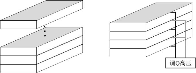
[0025] A low-voltage stacked lithium niobate electro-optic Q switch, which is formed by stacking three rectangular lithium niobate crystal sheets, each crystal has a size of 3mm×9mm×18.8mm ( x x y x z ), z The axial direction is the direction of light transmission, x The axial direction is the direction of the electric field, and the specific steps are as follows:

[0026] (1) In order to reduce the axial deviation of the three crystals, first cut the crystal orientation into a size of 9mm×9mm×18.8mm ( x x y x z ) of the rough block, directional grinding on each side, and z The surface is roughly polished, and then the crystal is cut into three pieces according to the required size, and the cutting surface is directional ground, and then the chamfering angle of each crystal along the length direction is C0.5;

[0027] (2) Mark the positive and negative directions of each axis of the crystal, and each x The surface is polished and plated with Au / Ti electrodes, and the t...

Embodiment 2

[0031] A low-voltage stacked lithium niobate electro-optical Q switch, which is formed by laminating two rectangular lithium niobate crystal slices, and each crystal has a cut shape of , the size is 4.5mm×9mm×18.8mm (thickness t ×width b × length l ), the length direction is the direction of light transmission, and the thickness direction is the direction of electric field application. The specific steps are as follows:

[0032] (1) In order to reduce the axial deviation of the two crystals, the crystals are first The cutting direction is cut into a size of 9mm×9mm×18.8mm (thickness t ×width b × length l ) of the rough block, directional grinding on each surface, and roughly polishing the two ends of the length direction, then cutting the crystal into two pieces according to the required size, directional grinding on the cutting surface, and then chamfering the edges of each crystal along the length direction C0.5;

[0033] (2) Mark the positive and negative direction...


PUM

PropertyMeasurementUnit
thicknessaaaaaaaaaa
lengthaaaaaaaaaa
widthaaaaaaaaaa

Abstract

The invention provides a low-voltage laminated lithium niobate electro-optical Q switch, which is formed by stacking several rectangular thin-sheet lithium niobate crystals along the thickness direction, and the cutting shape, size, and film coating of each crystal are exactly the same , the thickness direction of the lithium niobate crystal is the electric field direction, the length direction is the light transmission direction, and the two crystal faces of each crystal in the thickness direction are coated with electrodes. The present invention superimposes a plurality of rectangular thin slices and adopts the method of parallel power supply, under the condition of ensuring the same light aperture, the half-wave voltage can be reduced several times, which is beneficial to practical application.

Description

technical field [0001] The invention relates to the field of pulsed laser Q-switching devices, in particular to a low-voltage laminated lithium niobate electro-optical Q switch. Background technique [0002] Q-switching technology is currently one of the most common ways to obtain short pulse lasers, and its appearance is an important breakthrough in the history of high peak power laser development. Compared with other Q-switching technologies, electro-optic Q-switching technology has the advantages of active controllability, fast switching speed, strong turn-off capability, and high extinction ratio. It is easy to obtain stable high peak power and narrow pulse width laser output, and the peak power can reach several Hundreds of megawatts, and the output time can be precisely controlled, and high-precision synchronization between the laser and other linked instruments can be achieved. Therefore, the electro-optical Q switch has become the most widely used Q-switching switch...

Claims


Application Information

Patent Timeline
Patent Type & Authority Patents(China)
IPC IPC(8): H01S3/115
CPCH01S3/115
Inventor 商继芳杨金凤郝好山陈铃苏丽霞
Owner HENAN INST OF ENG
Why Eureka
Try Eureka