Deslagging method for shipbuilding plasma cutting platform

A cutting platform, plasma technology, applied in the direction of plasma welding equipment, manufacturing tools, welding equipment, etc., can solve the problems of high investment cost, damage to the steel plate protective paint, reduce the quality of parts, etc., to achieve good slag removal effect, slag removal The effect of low cost and convenient operation

Pending Publication Date: 2021-02-23
SHANGHAI JIANGNAN CHANGXING SHIPBUILDING
View PDF0 Cites 1 Cited by
  • Summary
  • Abstract
  • Description
  • Claims
  • Application Information

AI Technical Summary

Problems solved by technology

However, this method of cutting steel through high-temperature melting will produce a large amount of iron oxide residue on the cutting platform during the production process
Although part of the melted iron oxide can be blown away by technical means, it is inevitable that waste slag will stick to the sword grid under the platform, which will affect the cutting efficiency of the cutting machine. At the same time, it will also damage the protective paint of the steel plate too much and reduce the quality of the parts.
[0003] In this regard, the existing method is to use tools such as hammers to manually knock to achieve the purpose of slag removal, which consumes a lot of labor and the effect of slag removal is not ideal
There are a large number of automatic slag removal machines on the market today, and the slag removal effect is good, but the equipment is relatively cumbersome, the one-time investment cost is high, and the audience is small

Method used


Image

  • Deslagging method for shipbuilding plasma cutting platform
  • Deslagging method for shipbuilding plasma cutting platform
  • Deslagging method for shipbuilding plasma cutting platform

Examples


Embodiment 1

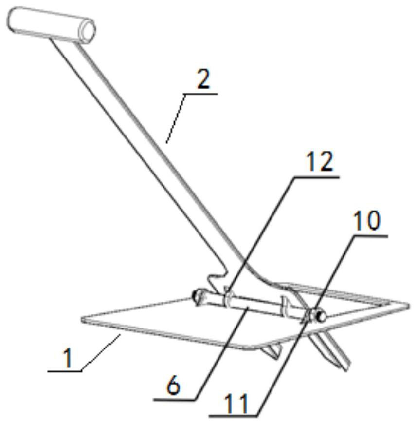
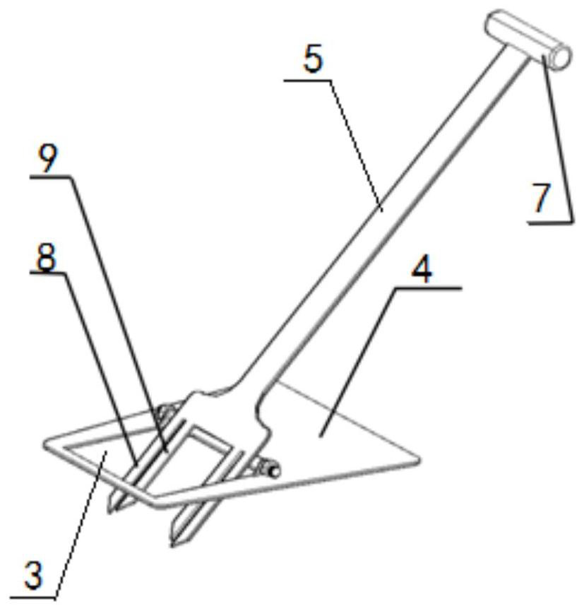
[0028] This embodiment provides a slag removal device for a shipbuilding plasma cutting platform, which includes a support part 1 and a slag removal part 2, and the support part 1 and the slag removal part 2 are integrally formed. The support part 1 is a flat plate, and one side of the support part 1 is provided with a rectangular installation hole 3, and the support part 1 on the opposite side of the installation hole 3 is a support platform 4, and the side of the support platform 4 connected to the installation hole 3 is installed with a shaft 6.

[0029] The slag removal part 2 includes a slag removal rod 5 and a slag removal head. The slag removal head is arranged at the end of the slag removal rod 5. Both sides of the slag removal rod 5 are provided with a first saber tooth 8 and a second saber tooth 9. A slag-removing tooth groove is formed between one saber tooth 8 and the second saber tooth 9, and the slag-removing tooth groove is used for snapping the sword bars, and ...

Embodiment 2

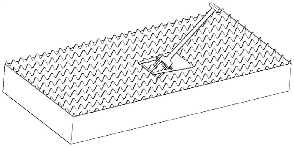
[0034] This embodiment provides a method for removing slag on a plasma cutting platform for shipbuilding, including the following steps:

[0035] Select the direction in which the sword grid bars of the plasma cutting platform are continuously penetrated, place the tooling, adjust the placement position, and rotate the slag removal rod 5 so that the two first saber teeth 8 can fall on the outer sides of the two adjacent sword grid bars, so that the two second sword teeth The second saber tooth 9 can fall on the inner side of two adjacent sword bars. After turning the slag removal lever 5 to make the slag removal alveolar reach the bottom, turn the slag removal lever 5 again to make the slag removal alveolar rotate upwards to clean out the slag removal alveolar. The molten slag on the sword bars causes the support platform 4 to lose stability up and down at the same time, so that the device moves forward and reciprocates to achieve the effect of cleaning the molten slag.


PUM


Abstract

The invention discloses a deslagging method for a shipbuilding plasma cutting platform. The method comprises the following steps that the continuous through direction of sword grid bars of the plasmacutting platform is selected, a deslagging device is placed, the placing position is adjsuted, a deslagging rod is rotated, two first sword teeth can fall on the outer sides of the two adjacent swordgrid bars, two second sword teeth can fall on the inner sides of the two adjacent sword grid bars, after the deslagging rod is rotated to enable a deslagging tooth groove to reach the lowest position,the deslagging rod is rotated again, the deslagging tooth groove is rotated upwards, and molten slag attached to the sword grid bars is removed; meanwhile, a supporting platform is unstable up and down, so that the device moves forwards, the process is repeated, and the effect of cleaning the molten slag is achieved. According to the deslagging method, the structure is simple, manufacturing is easy, operation is convenient, the molten slag adhering to the sword grid bars of the plasma cutting platform is pried away according to the lever principle, the molten slag removing effect is good, andthe deslagging cost is low.

Description

technical field [0001] The invention belongs to the technical field of shipbuilding, and in particular relates to a method for removing slag on a plasma cutting platform for shipbuilding. Background technique [0002] In the process of ship construction, a cutting platform is required to cut blanking steel plates and provide a large number of parts for the subsequent production area. As a processing method for cutting high-temperature molten steel, plasma cutting has high efficiency and is used by a large number of shipyards for steel blanking. However, this method of cutting steel through high-temperature melting will generate a large amount of iron oxide residue on the cutting platform during the production process. Although part of the melted iron oxide can be blown away by technical means, it is inevitable that waste slag will adhere to the sword grid under the platform, which will affect the cutting efficiency of the cutting machine, and will also damage the protective...

Claims


Application Information

Patent Timeline
IPC IPC(8): B23K10/00
CPCB23K10/00
Inventor 郑京浩于东海余伟瞿成钢
Owner SHANGHAI JIANGNAN CHANGXING SHIPBUILDING
Why Eureka
Try Eureka