
Camera module shell

A camera module and housing technology, applied in auxiliary devices, auxiliary welding equipment, welding/cutting auxiliary equipment, etc., can solve the problems of substandard welding depth, easy deviation of the upper shell, and poor air tightness, etc. Achieve the effects of convenient processing and assembly, excellent fool-proof function, and simple structure

Pending Publication Date: 2021-02-23
ZHEJIANG SUNNY SMARTLEAD TECH CO LTD
View PDF0 Cites 2 Cited by
  • Summary
  • Abstract
  • Description
  • Claims
  • Application Information

AI Technical Summary

Problems solved by technology

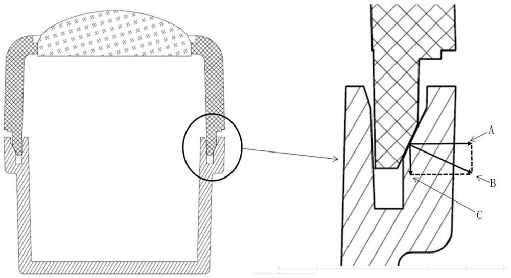
At this time, due to the existence of the above gap, the upper shell is very easy to shift
The housing tank is generally ring-shaped, so the deviation of the upper shell to one side will inevitably cause the other side to rise along the inclined housing tank outer wall, so that the welding depth of this side is not up to standard, and the airtightness is not good

Method used


Image

  • Camera module shell
  • Camera module shell
  • Camera module shell

Examples


Embodiment Construction

[0021] In order to more clearly describe the embodiments of the present invention or the technical solutions in the prior art, the following will briefly introduce the drawings that are used in the embodiments. Apparently, the drawings in the following description are only some embodiments of the present invention, and those skilled in the art can also obtain other drawings according to these drawings without creative efforts.

[0022] When describing the embodiments of the present invention, the terms "vertical", "transverse", "upper", "lower", "front", "rear", "left", "right", "vertical", " The orientation or positional relationship expressed by "horizontal", "top", "bottom", "inner" and "outer" is based on the orientation or positional relationship shown in the relevant drawings, which are only for the convenience of describing the present invention and simplifying the description, and It is not to indicate or imply that the device or element referred to must have a particu...


PUM


Abstract

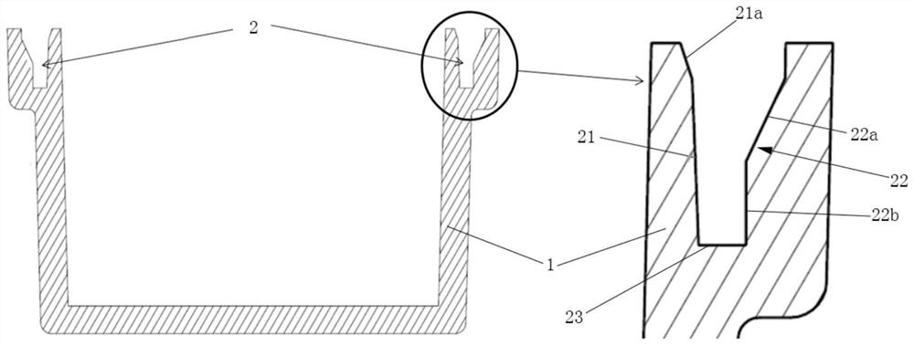
The invention relates to a camera module shell. The camera module shell comprises a shell body (1), one side of the shell body (1) is open, an annular containing groove (2) is formed in the end face of the open side of the shell body (1), the containing groove (2) is composed of an inner groove wall (21), an outer groove wall (22) and a groove bottom (23), and the inner groove wall (21) obliquelyextends outwards from the opening side of the shell body (1) to the other side. According to the camera module shell, the inner groove wall in the containing groove is inclined, so that an upper shellcannot deviate in the welding process, and the anti-stay function is achieved.

Description

technical field [0001] The invention relates to a camera module case. Background technique [0002] The side non-destructive laser welding equipment is mainly composed of laser, optical fiber, fixture and so on. The principle is that through the optical fiber tube, the laser light is transmitted through the transmission material, absorbed by the absorption material, and heat is generated to weld the absorption material and the transmission material to complete the welding. Generally speaking, there are design tolerances in the structural design parts of the upper and lower shell parts, the difference in the processing size of the part mold and the difference in the shape of the parts will cause the welding surface of the upper and lower shells to be uneven, and the welding surface of the upper and lower shells will produce a fit gap. Parts are incompletely welded, or even poorly welded, and the waterproof and NG sealing is poor. [0003] The side laser welding process requ...

Claims


Application Information

Patent Timeline
Patent Type & Authority Applications(China)
IPC IPC(8): B23K37/04B23K37/00
CPCB23K37/00B23K37/0426
Inventor 方必军许银锋张扣文薛狄军
Owner ZHEJIANG SUNNY SMARTLEAD TECH CO LTD
Learn More