
Efficient PPR pipe cutting device

A cutting device and high-efficiency technology, which is applied in metal processing and other directions, can solve the problems of inability to cut in batches and cannot be fixed, so as to achieve good cutting, improve work efficiency, and ensure the effect of cutting quality

Active Publication Date: 2021-02-23
浙江卫德管业有限公司
View PDF5 Cites 2 Cited by
  • Summary
  • Abstract
  • Description
  • Claims
  • Application Information

AI Technical Summary

Problems solved by technology

[0005] In order to overcome the disadvantages of manual transmission, inability to fix, and batch cutting in the prior art, the technical problem to be solved is to provide a high-efficiency cutting device for PPR pipes that can be automatically and efficiently conveyed, batch-cut and stably fixed to solve the existing problems

Method used


Image

  • Efficient PPR pipe cutting device
  • Efficient PPR pipe cutting device
  • Efficient PPR pipe cutting device

Examples


Embodiment 1

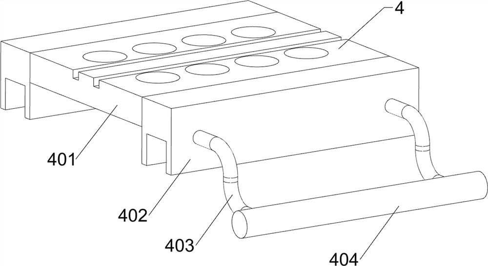
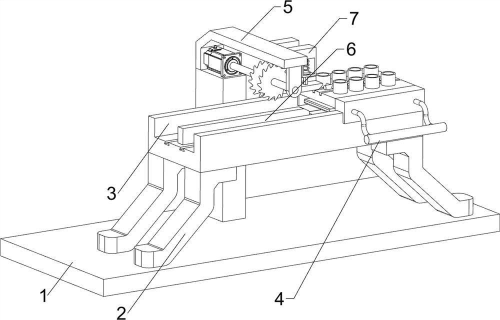
[0025] A kind of efficient cutting device for PPR pipe, such as figure 1 , figure 2 and image 3 As shown, it includes a base 1, a first bracket 2, a workbench 3, a sliding assembly 4 and a cutting assembly 5. The left and right sides of the upper side of the base 1 are symmetrically connected with the first bracket 2, while the upper side of the base 1 is The first bracket 2 is also connected in the middle of the front part, and the workbench 3 is connected between the upper side of the first bracket 2 at the front part. The sliding assembly 4 is arranged on the upper right side of the upper part of the workbench 3, and the cutting assembly is arranged on the upper side of the first bracket 2 at the rear. 5.

[0026] When the user needs to cut the PPR tube, first put the PPR tube into the sliding assembly 4, start the cutting assembly 5, then push the sliding assembly 4 to move to the left, drive the PPR tube to move to the left to the cutting assembly 5, and complete the ...

Embodiment 2

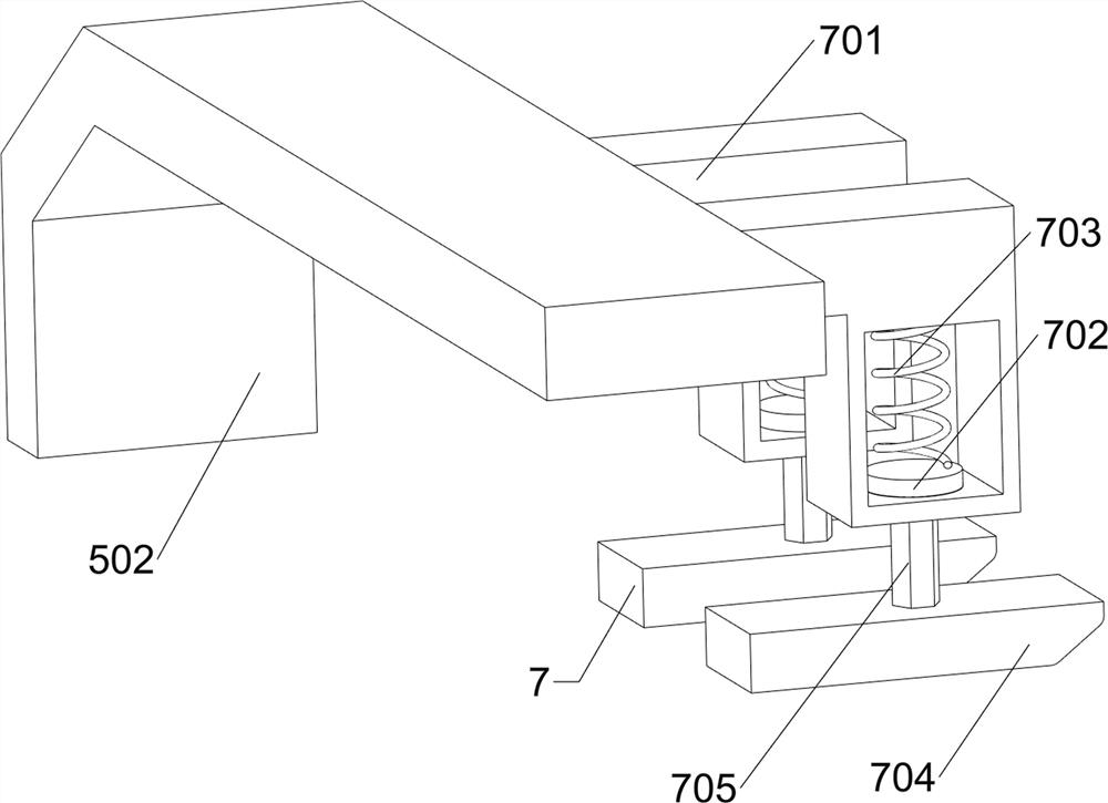
[0032] On the basis of Example 1, such as Figure 4 and Figure 5 As shown, it also includes a stabilizing assembly 6, and the stabilizing assembly 6 includes a first slide block 601, a first spring 602, a first movable plate 603, a first top block 604, a sleeve rod 605 and a first contact block 606, and the working table 3 The upper side of the lower part is connected with the first sliding block 601 in front and rear symmetrical sliding type, and the first spring 602 is connected with the left and right sides of the upper part of the first sliding block 601, and the first movable plate 603 is connected between the upper side of the first spring 602, and the second Eight first jacking blocks 604 are symmetrically connected front and back to the top of a movable plate 603, and the space between the jacking blocks 604 is even. Connected, the sleeve rod 605 passes through the upper opening of the rack 401, the sleeve rod 605 cooperates with the rack 401, and the middle of the l...


PUM


Abstract

The invention relates to a cutting device, in particular to an efficient PPR pipe cutting device. The efficient PPR pipe cutting device aims to achieve the aims of achieving automatic and efficient conveying, in-batch cutting and stable fixing. The efficient PPR pipe cutting device comprises a base, first supports, a workbench, a sliding assembly and a cutting assembly, the first supports are symmetrically connected to the left side and the right side of the front portion of the upper side of the base front and back, meanwhile, the first supports are connected to the middle of the rear portionof the upper side of the base, the workbench is connected between the upper sides of the first supports at the front portion, the sliding assembly is mounted at the right side of the upper portion ofthe workbench, and the cutting assembly is arranged at the upper sides of the first supports at the rear portion. According to the efficient PPR pipe cutting device, a grip is dragged to move leftwards to drive PPR pipes to move leftwards to make contact with a cutting knife to complete cutting, the effect of simply and conveniently conveying the PPR pipes in batches is achieved, feeding and discharging are completed in one step, and manpower is saved.

Description

technical field [0001] The invention relates to a cutting device, in particular to a high-efficiency cutting device for PPR pipes. Background technique [0002] PPR is the abbreviation of random polypropylene copolymer in English. PPR pipes are mainly used for the replacement of UPVC water supply pipes, aluminum-plastic pipes, PE pipes, PE-X pipes, and PE-RT pipes. Due to the strength of its own raw materials and high temperature resistance Get a good guarantee, so as to become the main force of water pipe materials. In order to obtain different shapes of PPR pipes, it is necessary to cut the PPR pipes. [0003] The traditional high-efficiency cutting technology of PPR pipe is to hold the PPR pipe under the high-speed rotating cutting knife, put the PPR pipe under the cutting knife, so that the PPR pipe is cut, and the PPR pipe falls to the ground after cutting, and then the PPR pipe is made Unified collection, this method requires manual transfer of PPR tubes, which is lab...

Claims


Application Information

Patent Timeline
Patent Type & Authority Applications(China)
IPC IPC(8): B26D3/16B26D1/15B26D7/06B26D5/08B26D7/02B26D7/32
CPCB26D3/161B26D1/15B26D7/0616B26D5/086B26D7/02B26D7/32B26D2007/013
Inventor 卢兆源
Owner 浙江卫德管业有限公司
Learn More