Concrete pouring machine for tunnel secondary lining vault

A concrete and pouring machine technology, applied in the direction of tunnel lining, tunnel, shaft lining, etc., can solve the problems of cumbersome construction personnel, affect the pouring efficiency, and increase the labor intensity of construction personnel, so as to improve construction efficiency, improve pouring quality, The effect of easy operation

Inactive Publication Date: 2021-02-23
ZHENGZHOU YUNQI IND EQUIP TECH CO LTD
View PDF1 Cites 2 Cited by
  • Summary
  • Abstract
  • Description
  • Claims
  • Application Information

AI Technical Summary

Problems solved by technology

[0005] The object of the present invention is to provide a concrete pouring machine for the second lining vault of the tunnel, aiming to solve the problem that the concrete pouring machine for the tunnel second lining vault in the prior art will exit the concrete of the end formwork when pouring concrete Concrete can only be poured after part of the steel pipe of the delivery pipe is removed, which not only affects the pouring efficiency, but also is very cumbersome for the construction personnel, which increases the labor intensity of the construction personnel.

Method used


Image

  • Concrete pouring machine for tunnel secondary lining vault
  • Concrete pouring machine for tunnel secondary lining vault
  • Concrete pouring machine for tunnel secondary lining vault

Examples


Embodiment 1

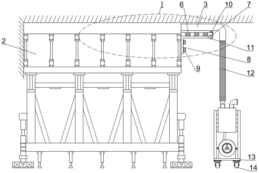
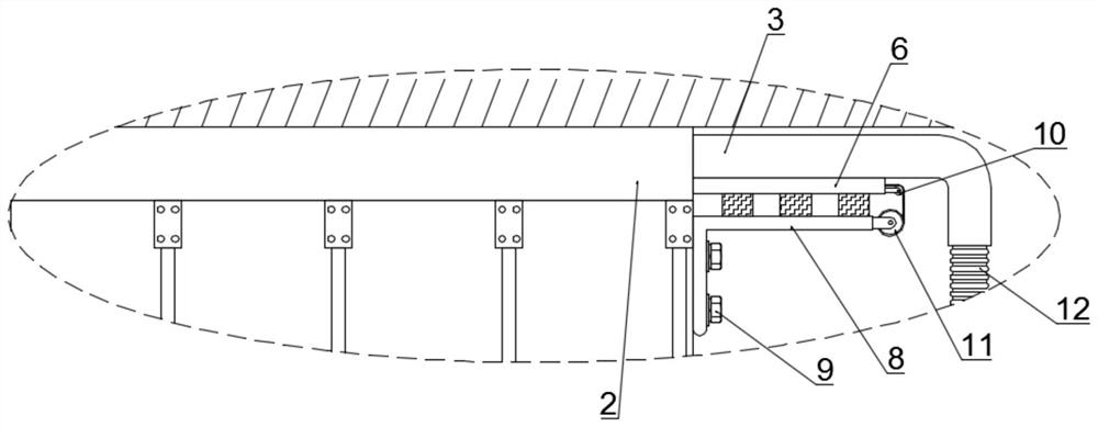
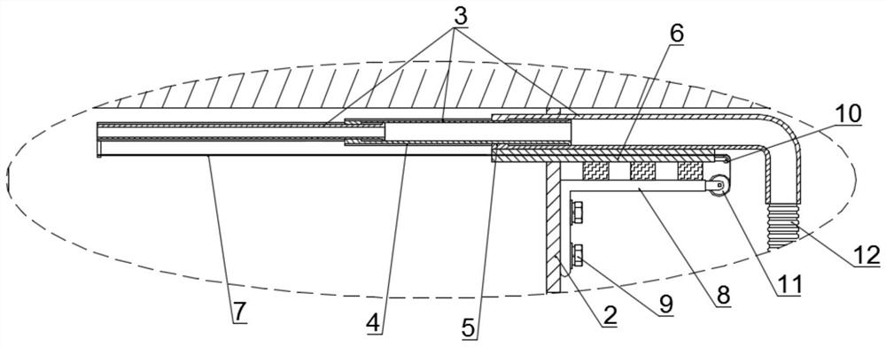
[0029] Such as Figure 1-3 As shown, a concrete pouring machine for the second lining vault of the tunnel includes a telescopic tube that can be inserted into the vault formwork 2, and a hollow sleeve 6 is fixedly connected to the surface of the telescopic tube. When the telescopic tube is inserted into When entering the vault formwork 2, the hollow sleeve 6 is then inserted into the vault formwork 2, and the telescopic tube is composed of at least two mutually socketed pipe bodies 3, which run through the section of the vault formwork 2 side wall. The body 3 is connected to the discharge end of the concrete conveying device through the hose 12, and the pipe body 3 at the farthest end in the vault formwork 2 is connected with a steel wire rope 7, and the steel wire rope 7 extends through the hollow sleeve 6 to The outside of the vault template 2, a support platform assembly is detachably installed on the outer surface of the vault form 2, and a storage wheel 11 for accommodati...

Embodiment 2

[0036] Such as Figure 1-3 As shown, a concrete pouring machine for the second lining vault of the tunnel includes a telescopic tube that can be inserted into the vault formwork 2, and a hollow sleeve 6 is fixedly connected to the surface of the telescopic tube. When the telescopic tube is inserted into When entering the vault formwork 2, the hollow sleeve 6 is then inserted into the vault formwork 2, and the telescopic tube is composed of at least two mutually socketed pipe bodies 3, which run through the section of the vault formwork 2 side wall. The body 3 is connected to the discharge end of the concrete conveying device through the hose 12, and the pipe body 3 at the farthest end in the vault formwork 2 is connected with a steel wire rope 7, and the steel wire rope 7 extends through the hollow sleeve 6 to The outside of the vault template 2, a support platform assembly is detachably installed on the outer surface of the vault form 2, and a storage wheel 11 for accommodati...


PUM


Abstract

The invention provides a concrete pouring machine for a tunnel secondary lining vault, and relates to the technical field of tunnel construction. The concrete pouring machine comprises a telescopic pipe capable of being inserted into a vault formwork, and a hollow sleeve is fixedly connected to the surface of the telescopic pipe. When the telescopic pipe is inserted into the vault formwork, the hollow sleeve is inserted into the vault formwork in a following mode, the telescopic pipe is composed of at least two sections of pipe bodies which are connected in a sleeve mode, and the section, penetrating through the side wall of the vault formwork, of the pipe body is communicated with the discharging end of a concrete conveying device through a hose. Due to the fact that the positions of discharging ports of the pipe bodies can be controlled only by controlling starting of a first motor, the vault formwork can be more evenly filled with concrete discharged by the pipe bodies, and comparedwith the situation in the prior art that a spliced concrete conveying pipe needs to be frequently detached to change the pouring position of the concrete, operation is more convenient. The construction efficiency is further improved.

Description

technical field [0001] The invention relates to the technical field of tunnel construction, in particular to a concrete pouring machine used for the second lining vault of a tunnel. Background technique [0002] The construction method of the secondary lining of the tunnel generally uses a lining trolley and is equipped with a concrete delivery pump for pouring. In the prior art, the commonly used method for pouring concrete into the vault of the second lining of the tunnel is to open holes in the formwork of the vault with a distance of about 3 meters. Insert the nozzle of the concrete pump delivery pipe directly from the opening, and pour concrete from the inside out. After the pouring is completed, install the nozzle of the concrete pump delivery pipe on the head formwork, and rely on the pressure of the concrete pump to squeeze the concrete to the end of the pipe. the other end of the mouth. This kind of pouring process, due to the long pouring distance (about 10 meter...

Claims


Application Information

Patent Timeline
Patent Type & Authority Applications(China)
IPC IPC(8): E21D11/10
CPCE21D11/105
Inventor 不公告发明人
Owner ZHENGZHOU YUNQI IND EQUIP TECH CO LTD
Why Eureka
Try Eureka