
Intermittent alternate heat exchange method for loop heat pipe system

A loop heat pipe and heat pipe technology, applied in the field of heat pipes, can solve the problems of uncompact structure, uneven heat absorption, and low fluidity of the heat pipe waste heat utilization system, so as to achieve heating efficiency and descaling operation, increase vibration range, and improve The effect of heat transfer efficiency

Active Publication Date: 2021-02-23
ZHONGBEI UNIV
View PDF6 Cites 0 Cited by
  • Summary
  • Abstract
  • Description
  • Claims
  • Application Information

AI Technical Summary

Problems solved by technology

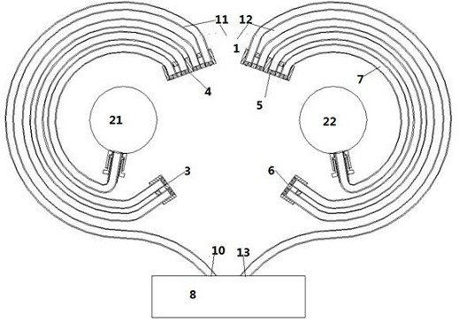
[0004] In the prior art, the shape of the heat pipe affects the heat-absorbing area of ​​the evaporating end, so the heat-absorbing range of the evaporating end is generally relatively small, and sometimes it is necessary to install multiple heat pipes in the heat source to meet the heat-absorbing demand; and when there are multiple evaporating ends, Because each evaporation end is in a different position of the heat source, it will produce uneven heat absorption.
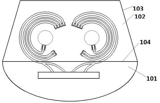
In the prior art, the waste heat utilization heat pipe device always extends the condensation end to the outside of the pipe, which occupies the external area, making the heat pipe waste heat utilization system not compact
[0005] In addition, elastic vibrating tube bundles are widely used in waste heat heat exchange. In the application, it is found that continuous heating will lead to the stability of the fluid in the internal heat pipe device, that is, the fluid is not flowing or has little fluidity, or the flow rate is stable, resulting in coil coils The vibration performance is greatly reduced, which affects the descaling of the coil and the efficiency of the heating

Method used


Image

  • Intermittent alternate heat exchange method for loop heat pipe system
  • Intermittent alternate heat exchange method for loop heat pipe system
  • Intermittent alternate heat exchange method for loop heat pipe system

Examples


Embodiment Construction

[0031] The specific embodiments of the present invention will be described in detail below with reference to the accompanying drawings.

[0032] In this article, if there are no special instructions, when it comes to formulas, " / " means division, and "×" and "*" mean multiplication.

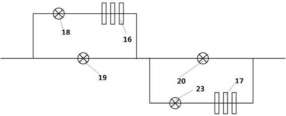
[0033] figure 1 A schematic diagram of the pipeline structure of the waste heat utilization loop heat pipe of the present invention is disclosed. like figure 1 As shown, the flue gas pipeline 101 includes two bypass pipelines, a first bypass pipeline and a second bypass pipeline, wherein a first valve 18 and a heat pipe 16 are respectively set on the first bypass pipeline, and the first bypass pipeline is provided with a first valve 18 and a heat pipe 16 respectively. A second valve 19 is provided on the flue gas pipe 101 corresponding to the pipeline. By setting the first valve 18 and the second valve 19, it is possible to control whether the flue gas passes through the heat pipe 16 for waste ...


PUM


Abstract

The invention provides an intermittent alternate heat exchange method for a loop heat pipe system. Within a period time T, the heat exchange manner of a first heat pipe and a second heat pipe is as follows; in a half period of 0-T / 2, a first valve and a third valve are opened, and a second valve and a fourth valve are closed, so that flue gas enters the first heat pipe to be subjected to heat exchange; and in a half period of T / 2-T, the second valve and the fourth valve are opened, and the first valve and the third valve are closed, so that the flue gas enters the second heat pipe to be subjected to heat exchange. According to the method, heating is carried out by opening and closing the valves changing periodically, fluid can be frequently evaporated, expanded and contracted in an elasticpipe bundle of the heat pipes, and therefore the elastic pipe bundle is constantly driven to vibrate, and the heating efficiency and the descaling operation can be further realized. Internal fluid isprevented from flowing, and stability is formed.

Description

technical field [0001] The invention relates to a heat pipe technology, in particular to a heat pipe with a novel structure. Background technique [0002] Heat pipe technology is a heat transfer element called "heat pipe" invented by George Grover of Los Alamos National Laboratory in the United States in 1963. It makes full use of the principle of heat conduction and phase change medium. The fast heat transfer property of the heat pipe, the heat of the heating object is quickly transferred to the outside of the heat source through the heat pipe, and its thermal conductivity exceeds that of any known metal. [0003] Heat pipe technology has been widely used in aerospace, military and other industries before. Since it was introduced into the radiator manufacturing industry, people have changed the design thinking of traditional radiators and got rid of the single heat dissipation mode that relies solely on high-volume motors to obtain better heat dissipation effects. The use ...

Claims


Application Information

Patent Timeline
Patent Type & Authority Applications(China)
IPC IPC(8): F28D15/02F23J15/06
CPCF28D15/02F23J15/06Y02E20/30
Inventor 刘汉涛侯钦鹏张学清李海桥仝志辉江程刘一晟
Owner ZHONGBEI UNIV
Learn More