
Ultra-high-speed turbulence boundary layer drag reduction control method

An ultra-high-speed, boundary-layer technology that can be used in instrumentation, stochastic CAD, design optimization/simulation, etc., to solve problems such as limited research on turbulent friction

Active Publication Date: 2021-02-23
NAT UNIV OF DEFENSE TECH
View PDF8 Cites 5 Cited by
  • Summary
  • Abstract
  • Description
  • Claims
  • Application Information

AI Technical Summary

Problems solved by technology

[0005] Current research on turbulent boundary layer drag reduction mainly focuses on low Reynolds number and low-velocity flows, but research on turbulent friction in supersonic / hypersonic flows is still very limited

Method used


Image

  • Ultra-high-speed turbulence boundary layer drag reduction control method
  • Ultra-high-speed turbulence boundary layer drag reduction control method
  • Ultra-high-speed turbulence boundary layer drag reduction control method

Examples


Embodiment Construction

[0058] In order to make the purpose, technical solution and advantages of the present application clearer, the present application will be further described in detail below in conjunction with the accompanying drawings and embodiments. It should be understood that the specific embodiments described here are only used to explain the present application, and are not intended to limit the present application.

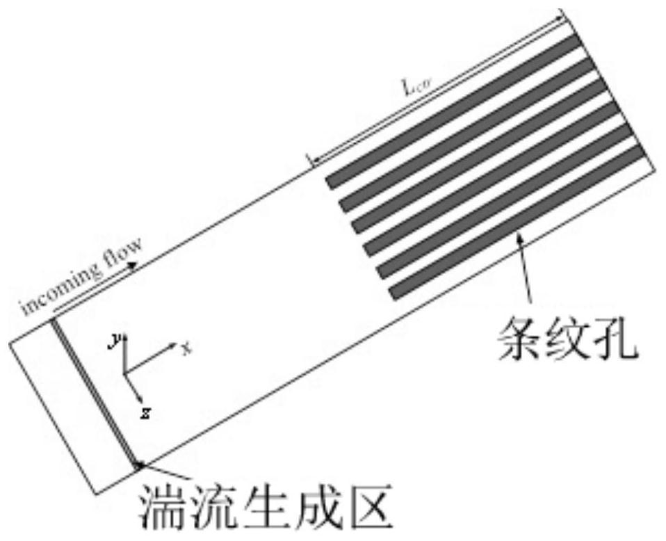
[0059] The ultra-high-speed turbulent boundary layer drag reduction control method provided by the present application is to arrange arrayed stripe holes along the flow direction on the wall surface of the ultra-high-speed aircraft forming the turbulent boundary layer. The wall surface blowing hot air device blows hot air to the wall surface through the stripe hole, and performs drag reduction control on the turbulent boundary layer of the ultra-high-speed aircraft.

[0060] In the above-mentioned ultra-high-speed turbulent boundary layer drag reduction control method, whe...


PUM


Abstract

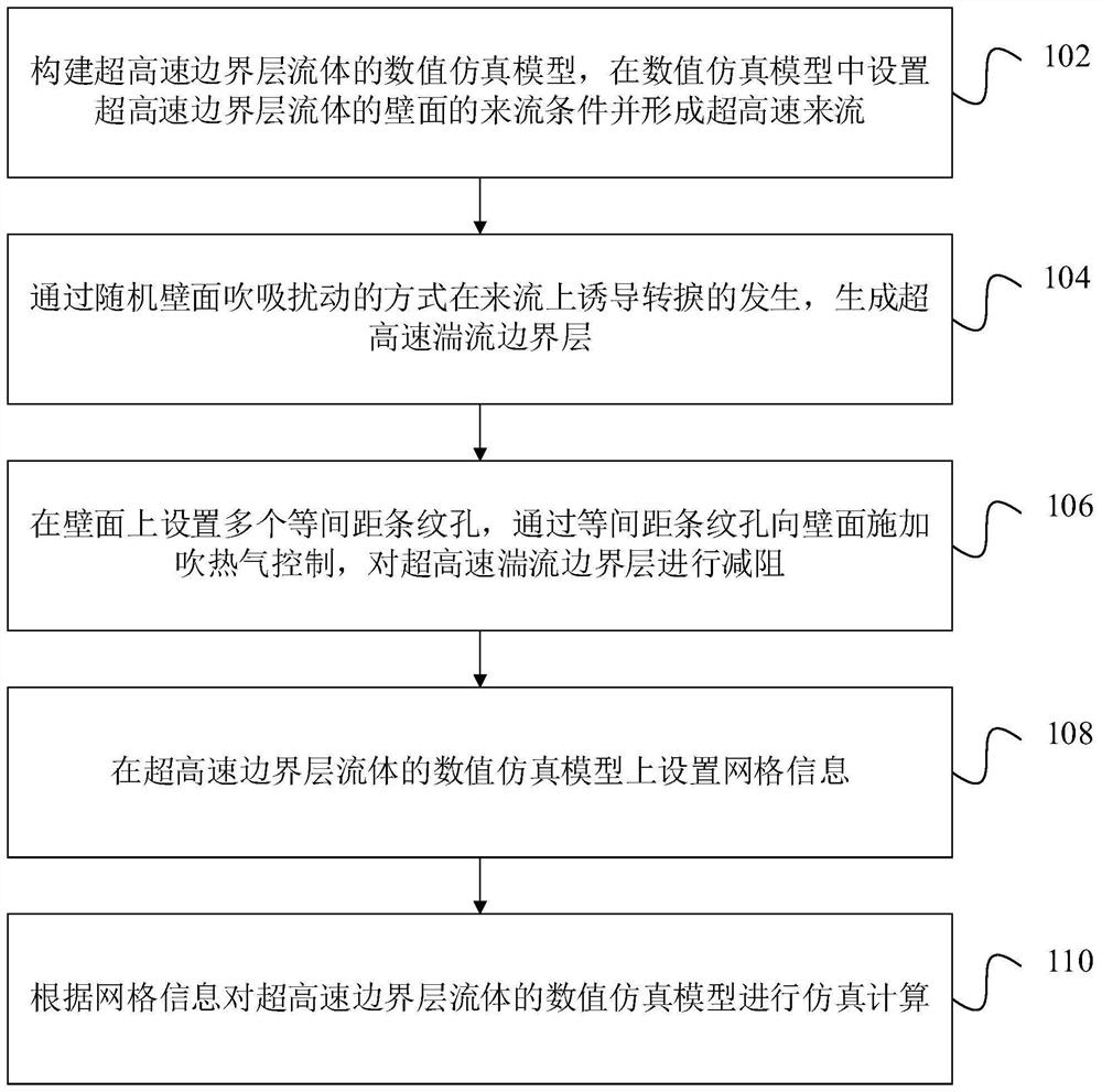
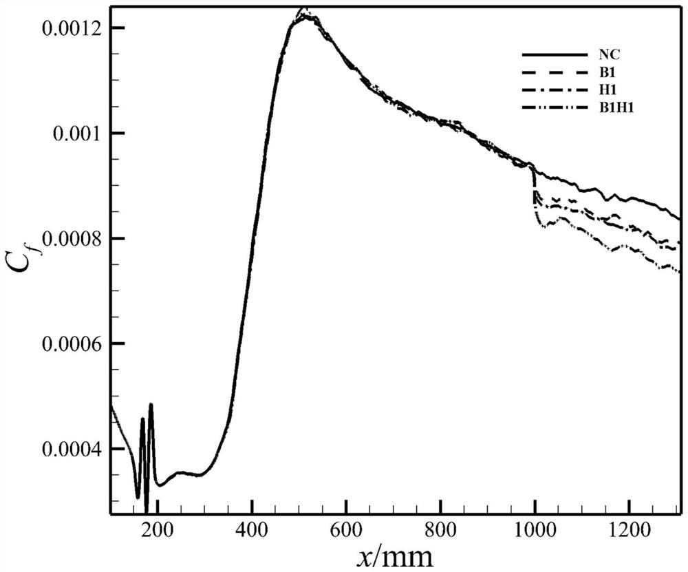
The invention relates to an ultra-high-speed turbulence boundary layer drag reduction control method, a simulation method, a simulation device, computer equipment and a storage medium. The ultra-high-speed turbulence boundary layer drag reduction control method comprises the steps that array type stripe holes are formed in the local wall face, forming a turbulence boundary layer, of an ultra-high-speed aircraft in the flow direction, and when the aircraft flies at an ultra-high speed, hot air is blown to the wall face from the stripe holes through a wall face hot air blowing device arranged onthe surface of the ultra-high-speed aircraft; and drag reduction control is performed on the turbulence boundary layer of the ultra-high-speed aircraft. The simulation method comprises the steps thata numerical simulation model of superspeed boundary layer fluid is constructed, incoming flow conditions are set, transition is induced, and a superspeed turbulence boundary layer is generated; hot air blowing control is applied to the wall surface through the equidistant stripe holes; simulation calculation is carried out on the numerical simulation model according to the set grid information, and the effectiveness and superiority of the ultrahigh-speed turbulence boundary layer drag reduction control method based on speed and temperature coupling are analyzed.

Description

technical field [0001] The present application relates to the technical field of drag reduction, in particular to a drag reduction control method for ultra-high-speed turbulent boundary layers, a simulation method, a simulation device, computer equipment and a storage medium. Background technique [0002] Hypersonic vehicle technology is a new commanding height in the field of aerospace technology in the 21st century, and it is also one of the country's major strategic needs. Hypersonic aircraft can maneuver at high speed in a large range in adjacent space, bypass the interception of missile defense systems, and carry out long-range and rapid strikes on important targets around the world. [0003] After decades of development, hypersonic technology has made major breakthroughs, but there are still many key problems to be solved. Turbulent drag reduction is one of the problems that need to be solved urgently. The hypersonic frictional resistance in the turbulent state is 3 t...

Claims


Application Information

Patent Timeline
Patent Type & Authority Applications(China)
IPC IPC(8): G06F30/15G06F30/28G06F111/08G06F111/10G06F113/08G06F119/14
CPCG06F30/15G06F30/28G06F2111/08G06F2111/10G06F2113/08G06F2119/14Y02T90/00
Inventor 罗振兵刘强邓雄王林周岩程盼彭文强
Owner NAT UNIV OF DEFENSE TECH
Learn More