Intelligent milling machine equipment
A milling machine and equipment technology, applied in the field of intelligent milling machine equipment, can solve the problems of a single shape of a workpiece clamped by a fixture, iron filings are not easy to clean, and processing equipment is not intelligent enough.
- Summary
- Abstract
- Description
- Claims
- Application Information
AI Technical Summary
Problems solved by technology
Method used
Image

Examples
specific Embodiment approach 1
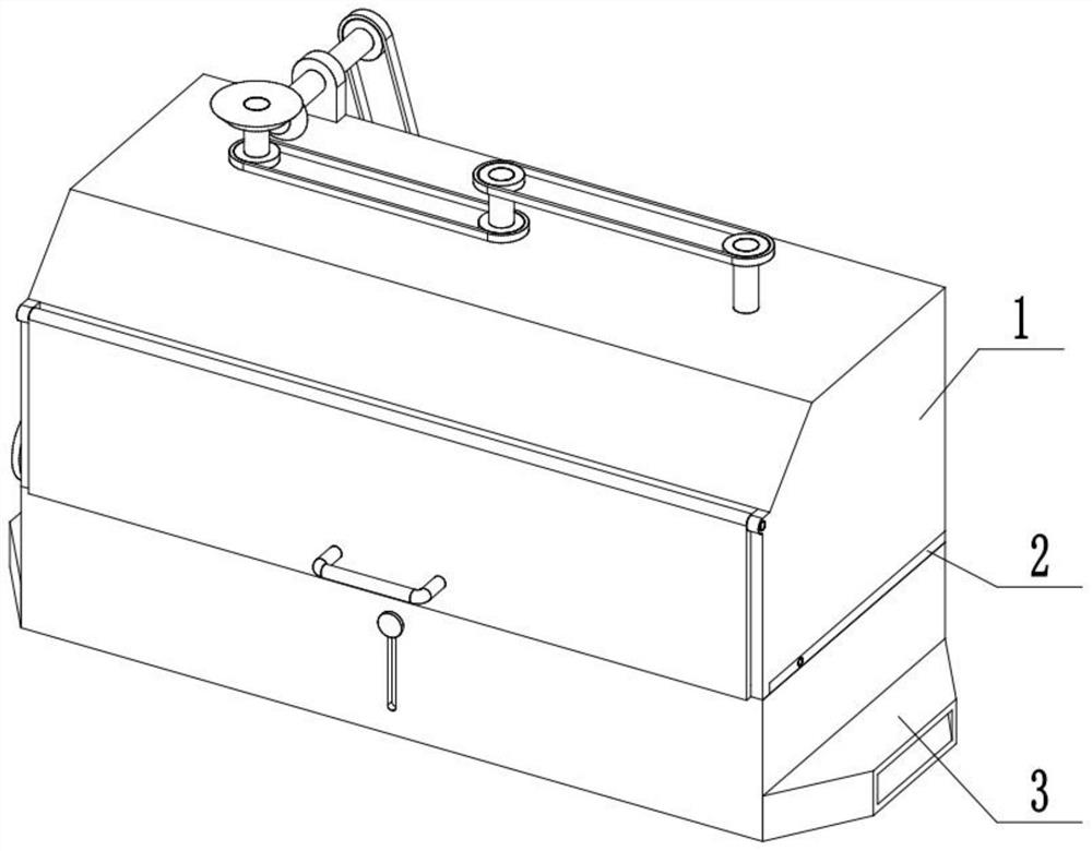
[0032] Combine below Figure 1-17 Describe this embodiment, an intelligent milling machine equipment, including a tool control assembly 1, a workpiece clamping assembly 2, and an iron chip cleaning and pressing assembly 3, the tool control assembly 1 is connected to the workpiece clamping assembly 2, and the tool control The combined body 1 and the workpiece clamping combined body 2 are all connected with the chip cleaning and pressing combined body 3 .
specific Embodiment approach 2
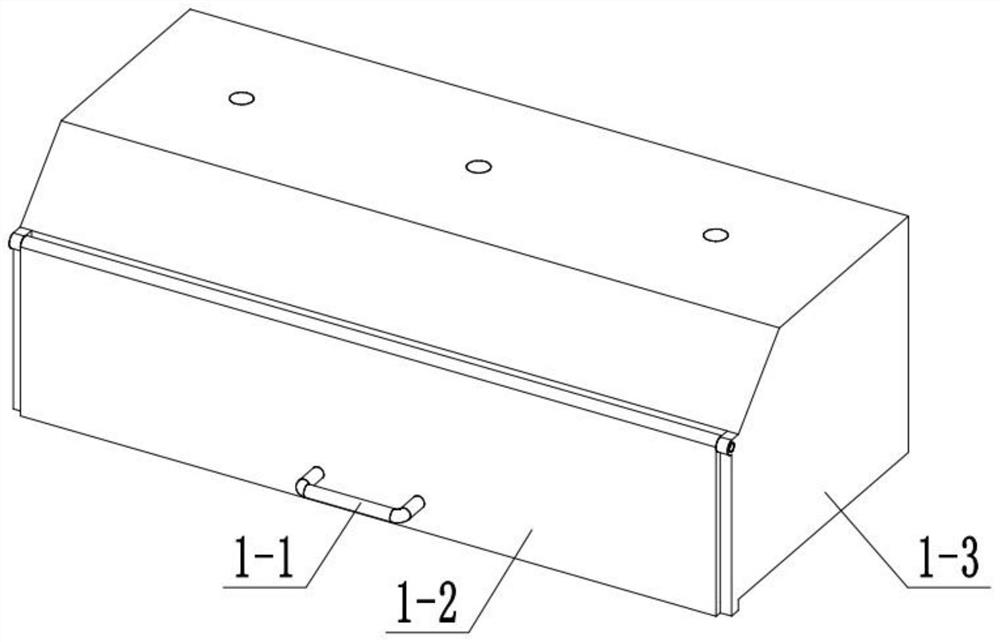
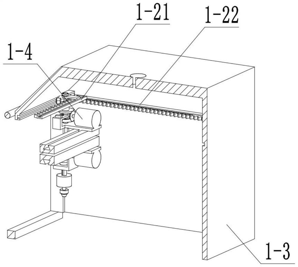
[0034] Combine below Figure 1-17 Describe this embodiment, this embodiment will further explain the first embodiment, the tool control assembly 1 includes a handle 1-1, a sliding door 1-2, a processing box 1-3, a servo motor I1-4, a servo motor I shaft 1-5, bevel gear Ⅰ 1-6, bevel gear Ⅱ 1-7, bevel gear Ⅲ 1-8, bevel gear Ⅲ chute 1-9, bevel gear Ⅱ chute 1-10, bevel gear Ⅱ shaft 1-11, sleeve 1-12, hydraulic system 1-13, oil pipe Ⅰ 1-14, oil pipe Ⅱ 1-15, hydraulic cylinder 1-16, ball joint telescopic rod 1-17, bevel gear inner ball groove 1-18, gear Ⅰ 1-19, gear Ⅱ 1 -20, rack Ⅰ1-21, rack Ⅱ1-22, sliding bracket Ⅰ1-23, sliding bracket Ⅱ1-24, servo motor Ⅰ bracket 1-25, servo motor Ⅰ sliding rail 1-26, servo motor Ⅱ 1-27, Servo motor Ⅱ shaft 1-28, bevel gear Ⅳ 1-29, servo motor Ⅱ shaft support 1-30, bevel gear Ⅴ 1-31, servo motor Ⅱ slide rail 1-32, thread barrel Ⅰ 1-33, threaded shaft with groove 1- 34. Servo motor Ⅲ 1-35, servo motor Ⅲ shaft 1-36, threaded barrel Ⅱ 1-37, fixture...
specific Embodiment approach 3
[0036] Combine below Figure 1-17 Describe this embodiment, this embodiment will further explain Embodiment 1, the workpiece clamping assembly 2 includes a turntable 2-1, a threaded shaft 2-2, a fixture bracket 2-3, a fixture slide rail 2-4, and a fixture 2 -5, slide bar 2-6, support plate 2-7 and spring 2-8, turntable 2-1 is connected with threaded shaft 2-2, threaded shaft 2-2 is rotationally connected with clamp support 2-3, clamp support 2 -3 is connected with the processing box 1-3, the fixture slide rail 2-4 is connected with the fixture support 2-3, the two fixtures 2-5 are all slidably connected with the fixture slide rail 2-4, and the threaded shaft 2-2 is provided with There are two threads with opposite directions of rotation, the two clamps 2-5 are threadedly connected with the two threads respectively, the slide rod 2-6 is slidingly connected with the clamp 2-5, the spring 2-8 is sleeved on the slide rod 2-6, The two ends of the spring 2-8 are respectively connec...
PUM
 Abstract
Description
Claims
Application Information
 - R&D
- Intellectual Property
- Life Sciences
- Materials
- Tech Scout
- Unparalleled Data Quality
- Higher Quality Content
- 60% Fewer Hallucinations
Browse by: Latest US Patents, China's latest patents, Technical Efficacy Thesaurus, Application Domain, Technology Topic, Popular Technical Reports.
© 2025 PatSnap. All rights reserved.Legal|Privacy policy|Modern Slavery Act Transparency Statement|Sitemap|About US| Contact US: help@patsnap.com