High-power-density soldering iron

A high power density, soldering iron technology, applied in the field of soldering iron core, can solve the problems of reducing the size and weight of high-frequency soldering irons, increasing the diameter of the soldering iron tip, increasing the output power, etc., to reduce thermal resistance, avoid temperature overshoot, The effect of shortening the distance

Inactive Publication Date: 2021-02-26
武汉文宇创新科技有限公司
View PDF6 Cites 0 Cited by
  • Summary
  • Abstract
  • Description
  • Claims
  • Application Information

AI Technical Summary

Problems solved by technology

Taking a 300W soldering iron as an example, the diameter of the soldering iron tip is usually more than 35 mm, and it is extremely inconvenient to operate when the operable space of the workpiece is limited; the weight of the soldering iron handle is usually more than 500 grams, and it is easy to get tired after long-term operation
[0005] The size and weight of the induction heating high-frequency soldering iron are reduced to a certain extent. During induction heating, the soldering iron tip is self-heated by eddy current and circulating current under the action of the high-frequency magnetic field generated by the high-frequency induction coil, and the working surface is far away from the heated part. The thermal conductivity of the soldering iron tip material is limited, further increasing the power requires increasing the diameter of the soldering iron tip, thus limiting the size reduction
[0006] The existing two types of soldering irons cannot reduce the volume under the premise of increasing the output power
[0007] Patent 95214195.7 designed an emergency arc electric soldering iron, using AC discharge to discharge between the electrode and the soldering iron tip, and heat the soldering iron tip. This design will generate the same heat on the soldering iron tip and the electrode, but the actual heat output is only the soldering iron tip , large loss

Method used


Image

  • High-power-density soldering iron
  • High-power-density soldering iron
  • High-power-density soldering iron

Examples


Embodiment Construction

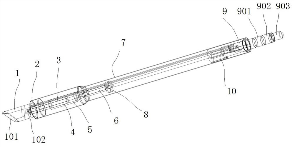
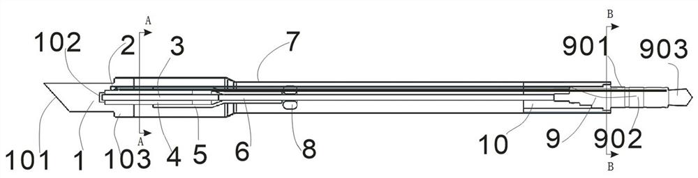
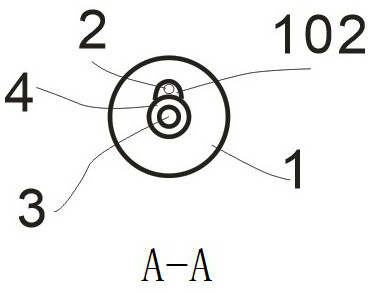
[0029] Such as Figure 1-Figure 4 As shown, the present invention is a high power density soldering iron, which includes a soldering iron head 1, the tail of which is installed on the end of the outer steel pipe 7, and the outer steel pipe 7 has a built-in soldering iron core; the rear end of the soldering iron head 1 is provided with a measuring A temperature sensor 2 and a ceramic tube 4 are installed in the temperature discharge hole 102. The ceramic tube 4 has a built-in discharge needle 3, and the discharge needle 3 is inserted into the temperature measurement discharge hole 102 of the soldering iron tip 1 through the ceramic tube 4.

[0030] The tail end of the outer steel pipe 7 is equipped with a quick-connect plug 9 connected to the built-in socket of the soldering iron handle, and the quick-connect plug 9 is connected with the outer steel pipe 7 through a plastic part 10 .

[0031] The power supply negative terminal 903 of the quick-connect plug 9 is connected to the...


PUM


Abstract

The invention relates to a soldering iron core, in particular to a high-power-density soldering iron. The soldering iron comprises a soldering iron head, wherein the tail of the soldering iron head isarranged at the end of an outer steel pipe; the soldering iron core is arranged in the outer steel pipe; a temperature measurement discharge hole is formed in the rear end of the soldering iron head;a temperature sensor and a ceramic tube are arranged in the temperature measurement discharge hole; a discharge needle is arranged in the ceramic tube; and the head of the discharge needle is inserted into the temperature measurement discharge hole through the center of the ceramic tube. The high-power-density soldering iron has the characteristics of high heating efficiency, compact structure, excellent temperature stability and the like.

Description

technical field [0001] The invention relates to a soldering iron core, in particular to a high power density soldering iron. Background technique [0002] Electric soldering iron is an essential tool in the electronics industry. It plays an irreplaceable role in development, production, and maintenance. The improvement of the performance of the soldering iron can greatly improve work efficiency. With the electronic power, the application of high-power modules is becoming more and more These devices are more and more valuable. When using a conventional low-power soldering iron to solder, the heating time can only be prolonged, resulting in a long heating time of the device, which is easy to be soldered or damaged. [0003] Existing soldering irons are mainly divided into two categories: power generation heating wire heating and induction heating according to the heating method: [0004] The electric heating type soldering iron heats the soldering iron tip by electrifying the...

Claims


Application Information

Patent Timeline
Patent Type & Authority Applications(China)
IPC IPC(8): B23K3/03
CPCB23K3/0338
Inventor 姚志文李丹
Owner 武汉文宇创新科技有限公司
Why Eureka
Try Eureka