
Multi-station cooperative regenerative braking energy utilization system and control method thereof

A technology of regenerative braking and energy storage system, which is applied to AC networks with the same frequency from different sources, power lines, AC network load balancing, etc., and can solve problems such as large investment costs and limited utilization of regenerative energy

Active Publication Date: 2021-02-26
SOUTHWEST JIAOTONG UNIV
View PDF7 Cites 0 Cited by
  • Summary
  • Abstract
  • Description
  • Claims
  • Application Information

AI Technical Summary

Problems solved by technology

However, the existing technology is mainly aimed at the utilization of regenerative energy within a single traction substation. When applied to the scene of multiple traction substations, due to the independence of each substation, the effect of regenerative energy utilization is limited, and there is a large investment cost.

Method used


Image

  • Multi-station cooperative regenerative braking energy utilization system and control method thereof
  • Multi-station cooperative regenerative braking energy utilization system and control method thereof
  • Multi-station cooperative regenerative braking energy utilization system and control method thereof

Examples


Embodiment

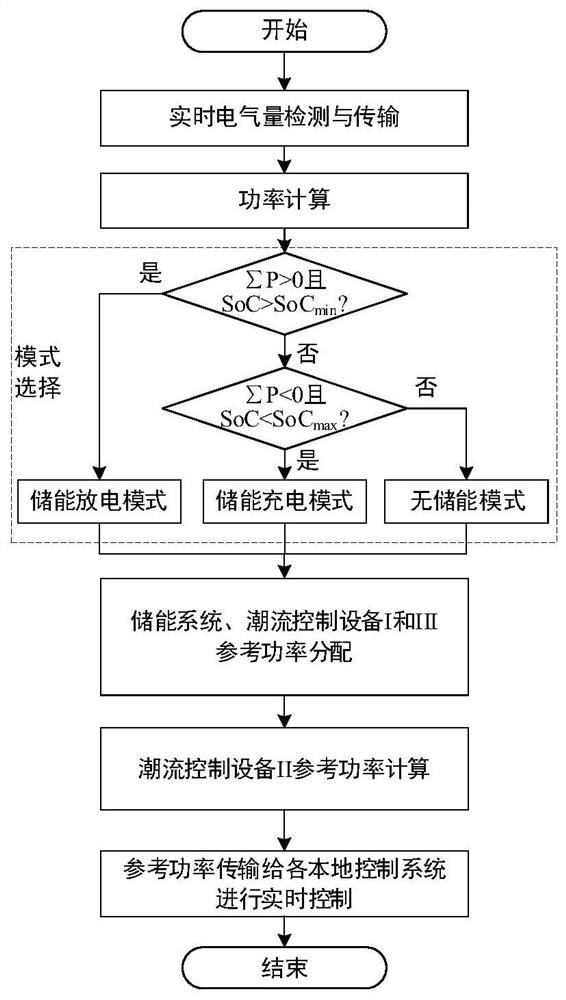
[0179] During energy control, set the SoC min 0.1, SoC max is 0.9, P max.dis 5MW, P ex-L 1MW.

[0180] In step 1, detect the left and right power supply arms of each substation, the power flow control equipment of each substation, and the power flow control equipment in substation II through the distributed voltage and current detection devices installed in the substation / divisional substation , Real-time voltage and current signals of the energy storage system;

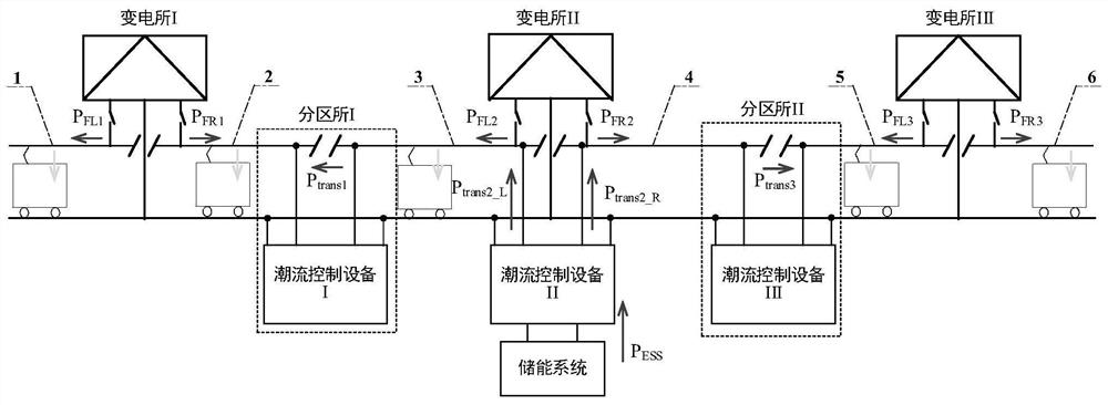
[0181] In step 2, the detection power is calculated to obtain: P in traction substation I FL1 2MW, P FR1 1MW, P in traction substation II FL2 3MW, P FR2 1MW, P in traction substation III FL3 -3MW, P FR3 is 1.5MW, the power flow control device I transfers power P trans1 = 2MW, transfer power P of power flow control equipment III trans3 =-1MW, the discharge power of the energy storage system is 3MW; in addition, the SoC is 0.5.

[0182] The internal load power of each traction substation can be calculated a...


PUM


Abstract

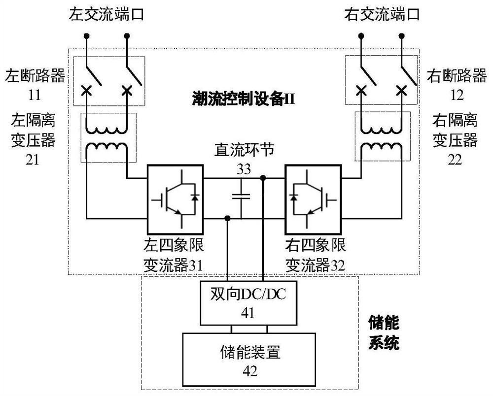
The invention discloses a multi-station cooperative regenerative braking energy utilization system and a control method thereof. The system comprises power flow control equipment I, power flow controlequipment II and power flow control equipment III which are formed by common direct-current links of left and right four-quadrant converters, wherein a left alternating-current port and a right alternating-current port of the power flow control equipment I are respectively connected to a right power supply arm I and a left power supply arm II at a section post I, and a left alternating-current port and a right alternating-current port of the power flow control equipment II are respectively connected to a left power supply arm II and a right power supply arm II at a substation II; a left alternating-current port and a right alternating-current port of the power flow control equipment III are respectively connected to a right power supply arm II and a left power supply arm III at the section post II; and an energy storage system connected to the direct current link of the power flow control equipment II. Power flow control equipment is used for power transfer, so that power exchange canbe carried out among a plurality of substations, and regenerative braking energy utilization paths are increased; power flow planning is carried out on different modes, and the utilization efficiencyof regenerative braking energy can be improved.

Description

technical field [0001] The invention relates to the field of electrified railway traction power supply systems, in particular to a multi-station coordinated regenerative braking energy utilization system and a control method thereof. Background technique [0002] In recent years, in my country's electrified railways, modern AC drive locomotives using regenerative braking have been used on a large scale, making the traction power supply system contain a large amount of regenerative braking energy. At present, a large amount of regenerative energy is directly returned to the power system, which reduces the energy utilization efficiency of the railway system; and because the power quality of the regenerative braking energy directly returned to the power system is not high, the power system usually adopts the charging method of ignoring the return or adding the return. , making the operating costs of the railway sector increase. With the promotion of heavy-duty electrified rail...

Claims


Application Information

Patent Timeline
Patent Type & Authority Applications(China)
IPC IPC(8): B60M3/00B60M3/06H02J3/06H02J3/32
CPCB60M3/00B60M3/06H02J3/06H02J3/32
Inventor 胡海涛黄毅陈俊宇葛银波王科何正友
Owner SOUTHWEST JIAOTONG UNIV
Learn More