Buoy system

A buoy and buoy chamber technology, applied in the field of buoy systems, can solve the problems of unfavorable buoy integration monitoring equipment, large size of buoy module, unfavorable transportation and loading and unloading, etc., to achieve convenient transportation and loading and unloading, simplify the production process, and optimize the internal space structure Effect

Pending Publication Date: 2021-02-26
国家海洋局南海调查技术中心 +2
View PDF1 Cites 6 Cited by
  • Summary
  • Abstract
  • Description
  • Claims
  • Application Information

AI Technical Summary

Problems solved by technology

However, this patent simply splits the buoy body into multiple buoy modules, and the volume of the buoy module is still large, which is not conducive to transportation and loading and unloading. In order to make the buoy module fixedly connected, it is necessary to set up a buoy bracket and X in the center of the buoy. Shaped keel is used as support, which wastes a lot of space of the buoy, which is not conducive to the integration of various monitoring equipment on the buoy

Method used


Image

  • Buoy system
  • Buoy system
  • Buoy system

Examples


Embodiment 1

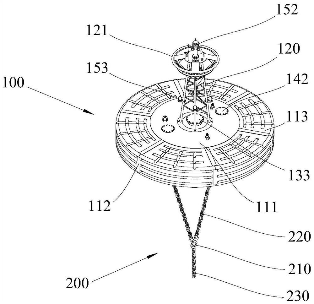
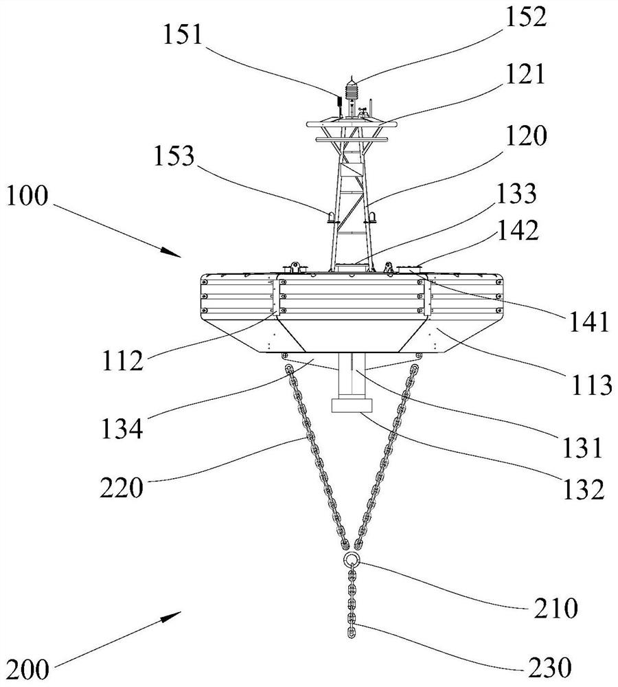
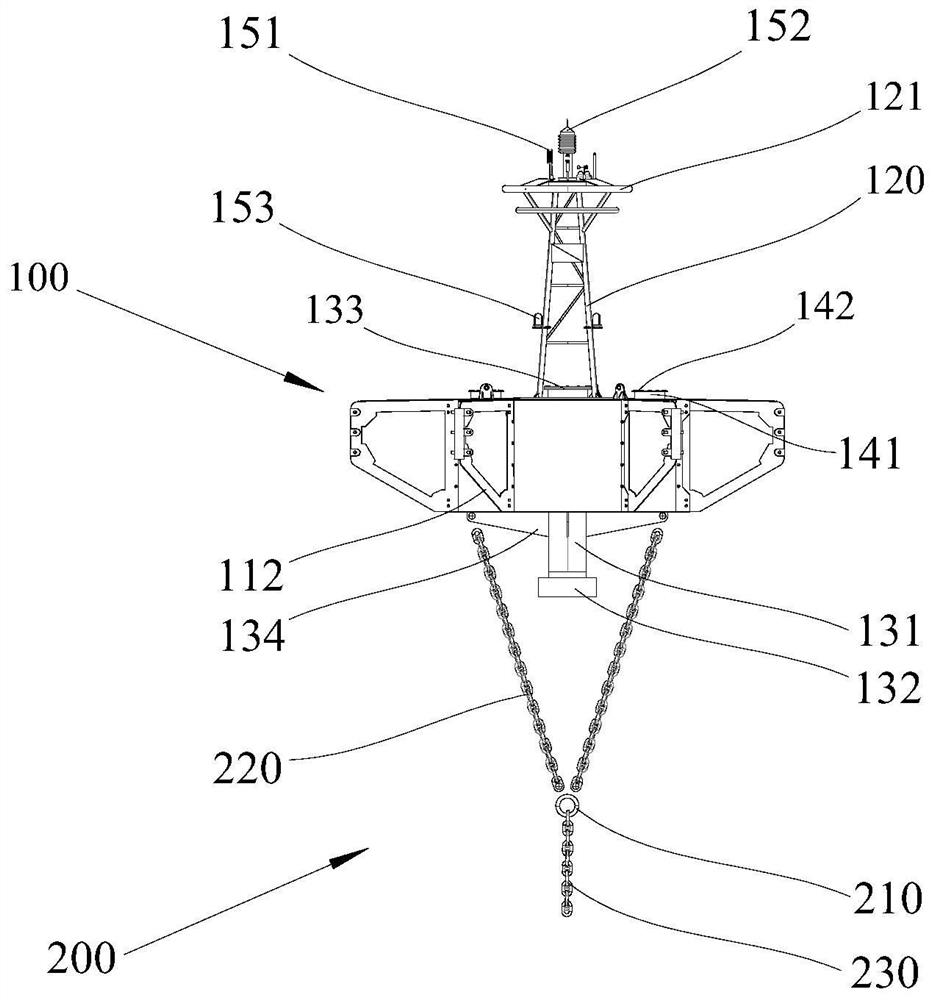
[0041] Such as Figure 1 to Figure 3 As shown, a buoy system provided in this embodiment includes a buoy body 100 and an anchoring device 200 .

[0042] The buoy body 100 includes: a main cabin 111, a mast 120, several brackets 112 and several outer wall components 113, the bottom of the main cabin 111 is provided with the mooring device 200, and the mast 120 is arranged on the main cabin 111 above, in this embodiment, the bracket 112 and the outer wall assembly 113 are made of stainless steel, as shown in the figure, the number of the bracket 112 and the outer wall assembly 113 are 6, and the bracket 112 surrounds the main cabin The body 111 is arranged on the side, and the outer wall assembly 113 is fixed on the bracket 112 through the fastener 113 on the bracket 112, and is fixed on the outer side of the main cabin body 111, and is connected with the bracket 112 and the main cabin body. The sides of 111 form a closed buoyancy chamber to provide buoyancy for the main cabin ...

Embodiment 2

[0052] The difference between this embodiment and Embodiment 1 is that the mooring device 200 chooses a mixed anchor rope structure instead of a full anchor chain structure, and one or more sections of cables are connected in the middle of the anchor chain 220, and the cables are connected to the anchor chain through a connecting member. The anchor chain 220 is connected, and the connecting member includes a cable sheath, an anti-pressure washer and at least one cable fixer. The section of the cable sheath is a curved tube, and a wear-resistant bushing and Reinforce the connecting plate, an anti-extrusion washer is arranged at the lower end of the cable sheath, a cable knot is arranged after the cable passes through the two through holes of the cable sheath and the anti-extrusion washer, and cables are fixed at intervals below the cable knot Device and cable knot, the end of cable below the last cable fixer and the cable body are provided with an end cable knot. The buoy main ...


PUM


Abstract

The present invention relates to a buoy system. The buoy system comprises: a buoy body; and an anchoring device, which is arranged below the buoy body and used for stabilizing the buoy body. The buoybody comprises a main cabin body, wherein the anchoring device is arranged at the bottom of the main cabin body; masts, which are arranged on a plurality of brackets above the main cabin body and surround the side surface of the main cabin body; and a plurality of outer wall assemblies, which are fixed to the brackets and fixed to the outer side edge of the main cabin body, wherein a closed floating chamber is defined by the outer wall assemblies, the brackets and the side face of the main cabin body. Structural modularization is achieved, the production process is simplified, transportation,loading and unloading are convenient, small and medium-sized fishing boats and engineering ships can be used for throwing and recycling, the ship using cost is reduced, the internal space structure ofthe buoy is optimized, various devices can be installed in the buoy, and the monitoring requirement is met.

Description

technical field [0001] The present invention relates to the technical field of ocean monitoring, and more specifically, to a buoy system. Background technique [0002] Marine environmental monitoring is an important means of developing marine economy, marine environmental protection, and marine disaster prediction and early warning. In the marine dynamics and ecological three-dimensional monitoring system, buoys are used as a hydrological system anchored on the sea surface and can be deployed near the coast or in the deep sea. Meteorological automatic monitoring equipment is essential, and it can work continuously for a long time under the extreme working environment conditions of the designed deployment sea area. The buoy is not only a platform for the installation of various meteorological and oceanographic monitoring instruments, but also a working platform for the collection and processing of monitoring data by the processor and data communication machine transmission. ...

Claims


Application Information

Patent Timeline
Patent Type & Authority Applications(China)
IPC IPC(8): B63B22/00B63B22/04B63B7/00
CPCB63B7/00B63B22/00B63B22/04B63B2022/006
Inventor 王伟平王东瑜刁文斌刘同木胡湛冯子旻
Owner 国家海洋局南海调查技术中心
Why Eureka
Try Eureka