
Large-span deck type concrete-filled steel tube arch bridge

A steel tube concrete and long-span technology, applied in arch bridges, bridges, truss bridges, etc., can solve the problems that cannot meet the requirements of strength, stiffness and stability

Pending Publication Date: 2021-02-26
SICHUAN DEPT OF TRANSPORTATION HIGHWAY PLANNING PROSPECTING & DESIGN RES INST
View PDF0 Cites 1 Cited by
  • Summary
  • Abstract
  • Description
  • Claims
  • Application Information

AI Technical Summary

Problems solved by technology

[0004] The purpose of the present invention is to overcome the disadvantages existing in the prior art: the structure of existing arch bridges cannot meet the strength, stiffness and stability requirements under larger spans, and to provide a large-span top-supporting concrete-filled steel tube arch bridge

Method used


Image

  • Large-span deck type concrete-filled steel tube arch bridge
  • Large-span deck type concrete-filled steel tube arch bridge
  • Large-span deck type concrete-filled steel tube arch bridge

Examples


Embodiment 1

[0039] This embodiment provides a long-span concrete-filled steel tube arch bridge, which is applied on a canyon, that is, the concrete-filled steel tube arch bridge in this embodiment is a valley-spanning bridge.

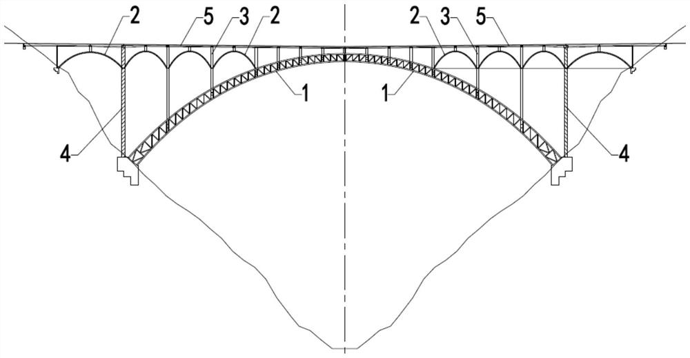
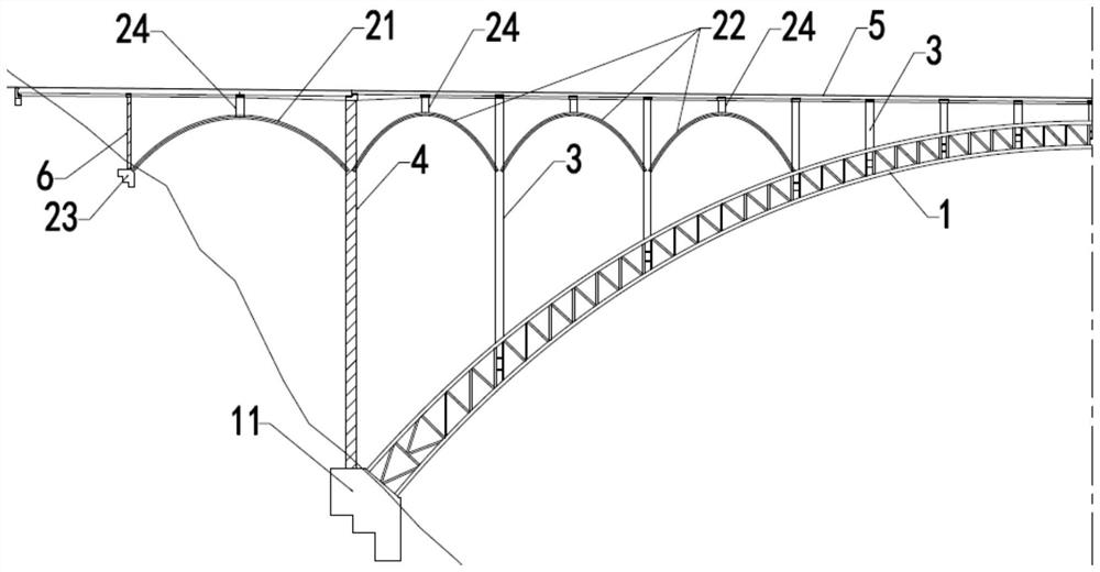
[0040] Such as figure 1 and figure 2 As shown, the concrete-filled steel tube arch bridge includes a main arch 1 , a main arch abutment 11 , an abdominal arch 2 , an abdominal arch abutment 23 , an upper column 3 of the main arch arch, a junction pier 4 and a deck beam 5 .

[0041] Described main arch abutment 11 is provided with two, and is respectively arranged on the foundation of canyon both sides, and described main arch 1 is arranged between described main arch abutment 11 on both sides and is formed by the main arch abutment 11 for support. In this embodiment, the main arch 1 adopts a steel pipe concrete truss structure as an example, the deck beam 5 is arranged on the main arch 1, and the deck beam 5 connects both sides of the canyon, thereby forming a c...

Embodiment 2

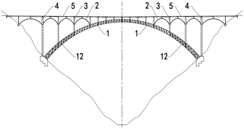
[0052] Such as image 3 , Figure 4 and Figure 5 As shown, on the basis of Embodiment 1, further, in this embodiment, the arch foot of the main arch 1 is provided with a stiffening area 12, and the abdominal tube of the main arch 1 of the stiffening area 12 is provided with Stiffened steel plate 121. Specifically, the web tubes between the corresponding upper chord 111 and lower chord 112 of the main arch 1 include oblique web tubes 114 and transverse web tubes 113, and the oblique web tubes 114 and transverse web tubes in the stiffening area 12 113, the upper chord 111 and the lower chord 112 are surrounded by several closed triangular frames arranged vertically, and a stiffening steel plate 121 is welded along the inner edge of the closed triangular frame. Through this arrangement, the bearing capacity of the main arch 1 of the stiffening area 12 is significantly improved.

[0053]On both sides of the main arch 1, since the upper pillars 3 of the main arch at the foot o...

Embodiment 3

[0057] Such as Figure 6 and Figure 7 As shown, on the basis of Embodiment 2, further, in the concrete-filled steel tube arch bridge described in this embodiment, the abdominal arch 2 is connected with tie rods 7, and the tie rods 7 are stretched on the abdominal arch 2 Among them, specifically, there are multiple tie rods 7 and they are connected to the abdominal arches 2 respectively. In this embodiment, the tie rods 7 are existing conventional steel strand tie rods. The purpose of setting the tie rods 7 is that the abdominal arch 2 can generate a horizontal thrust to the connected upper column 3 of the main arch, the main arch 1 or the junction pier 4 . In order to eliminate the influence of the horizontal thrust, we set the tie rod 7 at the abdominal arch 2, and balance the main arch 1, which is connected to the abdominal arch 2, by setting the tension of the tie rod 7. The horizontal thrust caused by the column 3 or the junction pier 4 on the main arch.

[0058] In th...


PUM


Abstract

The invention relates to a large-span deck type concrete-filled steel tube arch bridge. The concrete-filled steel tube arch bridge comprises a main arch, web arches, a junction pier, a bridge deck beam and a main arch spandrel column. The web arches are arranged on the two sides of the main arch in the longitudinal bridge direction respectively. In any side of the main arch, the web arch is divided into a first web arch and a second web arch, the first web arch is fixedly connected with a web arch support and the junction pier, the second web arch is connected with the junction pier, the mainarch and / or the main arch spandrel column, and the main arch spandrel column, the junction pier and the web arch jointly support the bridge deck beam. By means of the arrangement, the overall height of the main arch spandrel column is reduced, the dead weight of the bridge body is reduced to a certain degree, the stress requirement of the main arch is met, meanwhile, the engineering difficulty andthe engineering manufacturing cost are reduced, and the stability of the bridge body is improved. In addition, the web arch forms a longitudinal connecting structure between the main arch spandrel columns, and the longitudinal bridge direction stability of the main arch spandrel columns is further improved.

Description

technical field [0001] The invention relates to the technical field of arch bridges, in particular to a large-span top-supporting concrete-filled steel tube arch bridge. Background technique [0002] The CFST arch bridge is an excellent steel-concrete composite structure bridge. In the past 30 years, the CFST arch bridge technology has developed rapidly. More than 400 CFST arch bridges have been built across the country, making outstanding contributions to my country's economic development. In terms of span, the Sichuan Hejiang Yangtze River No. 1 Bridge, which is the largest span concrete-filled steel tube arch bridge, has reached 530m. With the further development of the economy, the current highway construction extends to the western mountainous area, facing more and more deep valleys and canyons. The technical and economical efficiency of long-span concrete-filled steel tube arch bridges is becoming more and more significant, and the demand is also increasing. [0003] ...

Claims


Application Information

Patent Timeline
Patent Type & Authority Applications(China)
IPC IPC(8): E01D4/00E01D19/00E01D6/00E01D101/26
CPCE01D4/00E01D6/00E01D19/00E01D2101/268
Inventor 牟廷敏赵艺程孙才志许诺邹圻梁健范碧琨康玲李胜倪春梅范翊李成君宋瑞年李畅何娇阳
Owner SICHUAN DEPT OF TRANSPORTATION HIGHWAY PLANNING PROSPECTING & DESIGN RES INST
Learn More