Assembly construction method of prefabricated comprehensive pipe gallery

A technology of integrated pipe gallery and construction method, applied in excavation, artificial islands, water conservancy projects, etc., can solve problems such as accidents, difficult construction management, impact on life travel, etc., to speed up production, achieve good implementation effects, and save prefabrication. Effects of costs and fees

Inactive Publication Date: 2021-02-26
YANGZHOU POLYTECHNIC INST
View PDF6 Cites 0 Cited by
  • Summary
  • Abstract
  • Description
  • Claims
  • Application Information

AI Technical Summary

Problems solved by technology

The main disadvantage of this cast-in-place method is that the construction period is long, and for road sections with high traffic pressure, it will have a great impact on people's life and travel
On the other hand, from the perspective of construction technology, the cast-in-place method requires multiple types of comprehensive construction on site, which makes the construction management on site more difficult, and the large number of personnel greatly increases the probability of accidents
Moreover, the cast-in-place method has high requirements for the construction environment, which makes it difficult to accurately control the quality of the construction, and the different construction environments of each section will easily lead to the occurrence of water seepage

Method used


Image

  • Assembly construction method of prefabricated comprehensive pipe gallery
  • Assembly construction method of prefabricated comprehensive pipe gallery
  • Assembly construction method of prefabricated comprehensive pipe gallery

Examples


Embodiment Construction

[0019] In order to make the object, technical solution and advantages of the present invention clearer, the present invention will be further described in detail below in conjunction with the accompanying drawings and embodiments. It should be understood that the specific embodiments described here are only used to explain the present invention, not to limit the present invention. In addition, the technical features involved in the various embodiments of the present invention described below can be combined with each other as long as they do not constitute a conflict with each other.

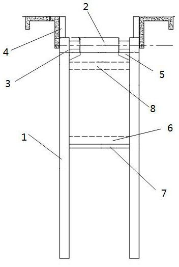
[0020] as attached figure 1 As shown, the excavation depth of the foundation pit is 6.55m, using 450mm thick prefabricated diaphragm wall 1, concrete strength grade C35, impermeability grade P6, each wall is 4.5m wide; prefabricated diaphragm wall 1 is 10.8m long, inserted 5.25m below the bottom of the pit , the insertion ratio is 1:0.8, the insertion length / the width of the foundation pit=1.81...


PUM


Abstract

The invention discloses an assembly construction method of a prefabricated comprehensive pipe gallery. The method includes the steps of (1) building an enclosure structure: excavating a foundation pit, and inserting prefabricated continuous walls into two sides of the foundation pit through hoisting; (2) constructing a supporting system: oppositely supporting the continuous walls by adopting horizontal steel pipes, and enclosing purlins by adopting double-spliced section steel; (3) constructing groove section joint interconnection: pre-burying U-shaped joint bars in grooves in the two ends ofthe prefabricated continuous walls, and immediately constructing root piles for filling after the prefabricated continuous walls are mounted in place; water stop strips are arranged on the outer edgesof the two sides of the grooves in the two ends of the prefabricated continuous walls; the distance between the joints on the outer sides of the grooves in the ends of the prefabricated continuous walls are not larger than 50 mm, and cement paste is adopted for conducting close joint operation on the distance between the joints; and (4) constructing connection between bottom plates and / or top plates and the prefabricated continuous walls. The comprehensive pipe gallery is constructed by performing truss operation on a conventional concrete floor, so that the prefabrication cost and expense are greatly saved, the production speed is increased, and the production benefit is improved.

Description

technical field [0001] The invention belongs to the field of pipe galleries, in particular to an assembly construction method of a prefabricated comprehensive pipe gallery. Background technique [0002] There are many cities in our country with dense population. In order to meet the needs of people's life in the city, it is necessary to build various types of pipe corridors according to different needs. Most of the traditional underground comprehensive pipe gallery enclosure structure adopts grading excavation, steel sheet piles, bored pipe piles, etc. In terms of specific construction, most of the integrated pipe galleries are made by pouring concrete on site. The main disadvantage of this cast-in-place method is that the construction period is long, and for road sections with high traffic pressure, it will have a great impact on people's life and travel. On the other hand, from the perspective of construction technology, the cast-in-place method requires multiple types o...

Claims


Application Information

Patent Timeline
Patent Type & Authority Applications(China)
IPC IPC(8): E02D29/045E02D5/10E02D17/04E02D5/12E02D5/14E02D29/16E02D31/02
CPCE02D5/10E02D5/12E02D5/14E02D17/04E02D29/10E02D29/16E02D31/02
Inventor 左春丽陈桂如曾晨岳金方
Owner YANGZHOU POLYTECHNIC INST
Why Eureka
Try Eureka