
Bare wall electromechanical wire box reinforcing method

A wire box and wall machine technology, which is applied in the field preparation of formwork/formwork/work frame, building components, construction, etc., can solve the problem of affecting the quality pass rate and visual quality of wire boxes, reducing work efficiency, displacement and box quality. Internal leakage and other problems, to achieve the effect of safe and reliable project quality, simple reinforcement structure, and reduce project cost

Inactive Publication Date: 2021-02-26
SHANGHAI BAOYE GRP CORP
View PDF5 Cites 0 Cited by
  • Summary
  • Abstract
  • Description
  • Claims
  • Application Information

AI Technical Summary

Problems solved by technology

The fixing of the embedded junction box is a key part of the embedded construction control of electrical pipelines. In the traditional embedded construction of electromechanical installation junction boxes, iron wire binding is often used to fix the junction box body. However, the above-mentioned junction box fixing method is not firm. , it is easy to cause displacement and grout leakage in the box. The displaced wire box will have a certain impact on the confirmation of the construction elevation and position in the later stage, and the concrete will easily enter the box and block the wire box after the junction box is displaced. If the chisel is corrected, it will be reworked and redone, which reduces the work efficiency and increases the installation cost. It also affects the quality pass rate and visual quality of the wire box after installation.
[0003] Therefore, there are above-mentioned inconveniences and problems in the known installation method of the clear water sheet wall machine wire box

Method used


Image

  • Bare wall electromechanical wire box reinforcing method

Examples


Embodiment 1

[0024]The method for reinforcing the wire box of the clear water wall machine of the present invention, by using round steel for reinforcement, includes the following steps:

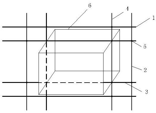
[0025]Step 1: Collect φ6mm round steel heads from the steel bar processing area, and cut different lengths according to actual needs. Prepare the wire box, electric welding machine, welding rod, and laser level; determine the axis position of the wire box according to the design drawings, use the laser level to locate, and mark the actual size of the junction box 6.

[0026]Step 2: Prepare the tools. Use a cutting machine to cut the φ6mm round steel according to the required length. The cut length is based on the spacing between the longitudinal and transverse steel bars of the shear wall on site, and the appropriate length is selected to ensure that the round steel crosses the structural steel bars, so that the wire box can be firmly fixed.

[0027]Step 3: When preparing to fix the wire box, communicate with the civil...


PUM


Abstract

The invention discloses a bare wall electromechanical wire box reinforcing method. The method is characterized by comprising the following steps that a, the axis position of the wire box is determinedaccording to the requirements of a design drawing; b, round steel is cut off through a cutting machine according to the needed length; c, the wire box is accurately placed on point positions according to the point positions measured in advance; d, the wire box is firmly clamped through the two cut-off round steel; e, the two pieces of fixed round steel is welded to nearby longitudinal structuralribs; f, the two pieces of cut round steel is placed on the left face and the right face of the wire box respectively to be tightly attached, and the wire box is firmly clamped; g, the two pieces of fixed round steel is welded and fixed to nearby transverse structural ribs, and the bare wall electromechanical wire box reinforcing is completed. The method has the advantages that a reinforcing structure is simple, construction is convenient, it is guaranteed that the exposed part of the embedded wire box is consistent with a bare wall veneer effect, the wire box is accurately positioned, the problems that in an existing method, forming is poor, damage is likely to happen and the unnecessary cost of later repair is caused are solved, and the engineering cost is reduced.

Description

Technical field[0001]The invention relates to a method for installing a wire box of a machine, in particular to a method for reinforcing the wire box of a clean water wall machine.Background technique[0002]The pre-embedding of the electrical and mechanical installation of the building is an important part of the electrical and mechanical installation of the building. The characteristics of the electrical pre-embedded box are the large number, complex layout, inadequate construction, and difficulty in subsequent correction. Therefore, it is necessary to strengthen the pre-embedded electrical Keep pre-buried work management. The fixation of the embedded junction box is a key part of the embedded construction control of the electrical pipeline. The traditional electromechanical installation junction box embedded construction often uses wire binding to fix the junction box body. However, the above-mentioned junction box fixing method is not firm , It is easy to cause displacement and le...

Claims


Application Information

Patent Timeline
Patent Type & Authority Applications(China)
IPC IPC(8): E04G15/06
CPCE04G15/061
Inventor 岳旭堂陈瑞武克辰蔡鲜平郭迎港
Owner SHANGHAI BAOYE GRP CORP
Learn More